The most primitive way to increase electric vehicle range is packing more battery cells beneath the floorboard. However, adding cells multiplies chassis weight, complicates wiring interconnects, and introduces a thermal management bottleneck. To scale cylindrical energy density without succumbing to excessive internal resistance, Tesla engineered the 4680 Tabless Cell and the Structural Battery (Cell-to-Chassis - CTC) platform.
This technical guide analyzes the solid-state physics of tabless current collection, structural honeycomb stress integration, and axial thermal dissipation models.
1. The 4680 Form Factor & Tabless Electrode Physics
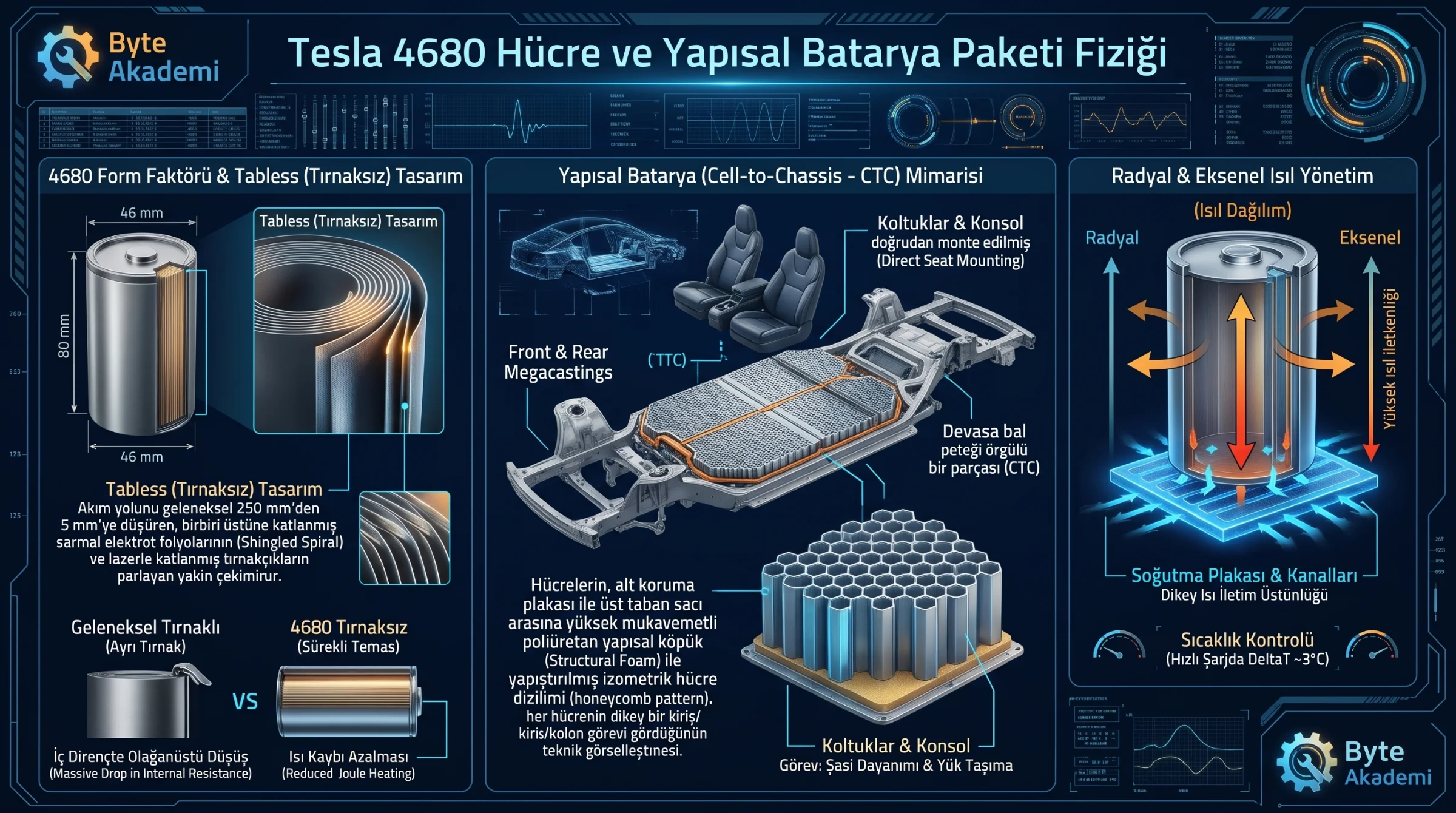
The designation denotes physical geometry: 46 mm in diameter and 80 mm in height, delivering 5.4 times the volumetric capacity of traditional 2170 cells. Historically, scaling cylindrical cells to this diameter introduced severe core overheating due to lengthy internal conduction paths.
Tesla solved this via the Tabless (Shingled Spiral) electrode design:
- Traditional Current Paths: Conventional 2170 cells rely on one or two welded metal tabs on the wound jelly roll. Electrons must travel the entire unwind length of the electrode foil—up to 250 mm—to reach the terminal. This long path produces elevated internal resistance (R) and intense Joule heating (I2R).
- 4680 Tabless Mechanism: Laser-etched conductive edges run continuously along the foil boundary. Once wound, these edges fold inward into a dense conductive contact pattern across the cell base. The maximum electrical path drops from 250 mm down to roughly 5 mm (the axial height of the foil).
  [CONVENTIONAL TABBED CURRENT PATH vs. 4680 TABLESS DESIGN]

  Conventional Cell : [Electrode Foil] --------------------> (Single Tab)  [Path: ~250 mm | Elevated R]
  4680 Tabless      : [Electrode Foil] |||||||||||||||||||| (Continuous)   [Path: ~5 mm   | Minimal R]
Shortening the electrical path by a factor of 50 significantly reduces equivalent series resistance (ESR). Lower ohmic resistance eliminates focal thermal hotspots within the core during DC fast charging.
Transforming the battery from dead weight into a load-bearing chassis structure fuses electrochemical energy storage directly with mechanical vehicle rigidity.
2. Cell-to-Chassis (CTC) Structural Integration
Standard electric vehicles utilize three stacked structural layers: individual cells within modules, modules bolted inside a pack enclosure, and the pack enclosure mounted below the body floor pan.
Tesla adopted aerospace fuselage principles by transforming the battery pack into a rigid honeycomb shear beam:
- Elimination of Modules: Intermediary module bulkheads, internal harnesses, and sub-controllers are removed, allowing direct cell packing.
- Structural Polyurethane Potting: Cells are encapsulated between an underside ballistic shield and the top floor plate using high-strength structural foam. Each steel 4680 can functions as a vertical structural pillar supporting shear and torsional loads.
- Direct Seat Mounting: The vehicle interior floorboard is removed entirely; front seats and center consoles bolt directly to the structural battery lid before vehicle marriage.
This approach increases overall vehicle torsional rigidity while eliminating roughly 370 separate components and hundreds of mechanical joints.
3. Thermal Management Dynamics
Prior-generation packs routed extruded aluminum serpentine cooling channels laterally between cell rows, relying predominantly on radial heat transfer across cylindrical walls.
The 4680 architecture redirects thermal modeling axially:
- Axial Heat Flow: Because the tabless foil ends maintain direct continuous contact with the can base, thermal conductivity is significantly higher along the vertical cylinder axis than through radial jelly-roll layers.
- Planar Heat Extraction: Integrated bottom cold plates and interleaving vertical channels draw heat directly from the high-conductivity ends, keeping delta temperatures within 3°C across adjacent cells during high C-rate cycling.