Visualize the electrical grid as a synchronous orchestra: synchronous generators rotate at exactly 50 or 60 Hz, synthesizing an immaculate, undistorted sinusoidal wave. When linear resistive elements consume this power, current scales in lockstep with voltage. However, the modern grid is heavily populated with non-linear power electronics—variable frequency drives (VFDs), server power supplies, silicon rectifiers, and arc furnaces—that chop continuous AC flow into rapid sub-cycle pulses.
This rapid switching distorts pure waveforms into jagged, destructive wave shapes known as Harmonics. Are harmonics exclusively a destructive phenomenon that overheats transformers and detonates power capacitors? Or are there critical engineering scenarios where specific harmonics are intentionally monitored to save grid equipment? This article examines the Fourier mechanics of harmonic distortion, triplen neutral current accumulation, active mitigation via Active Harmonic Filters (AHF), and life-saving 2nd harmonic inrush restraint in differential protection schemes.
1. Fourier Decomposition & Non-Linear Wave Distortion
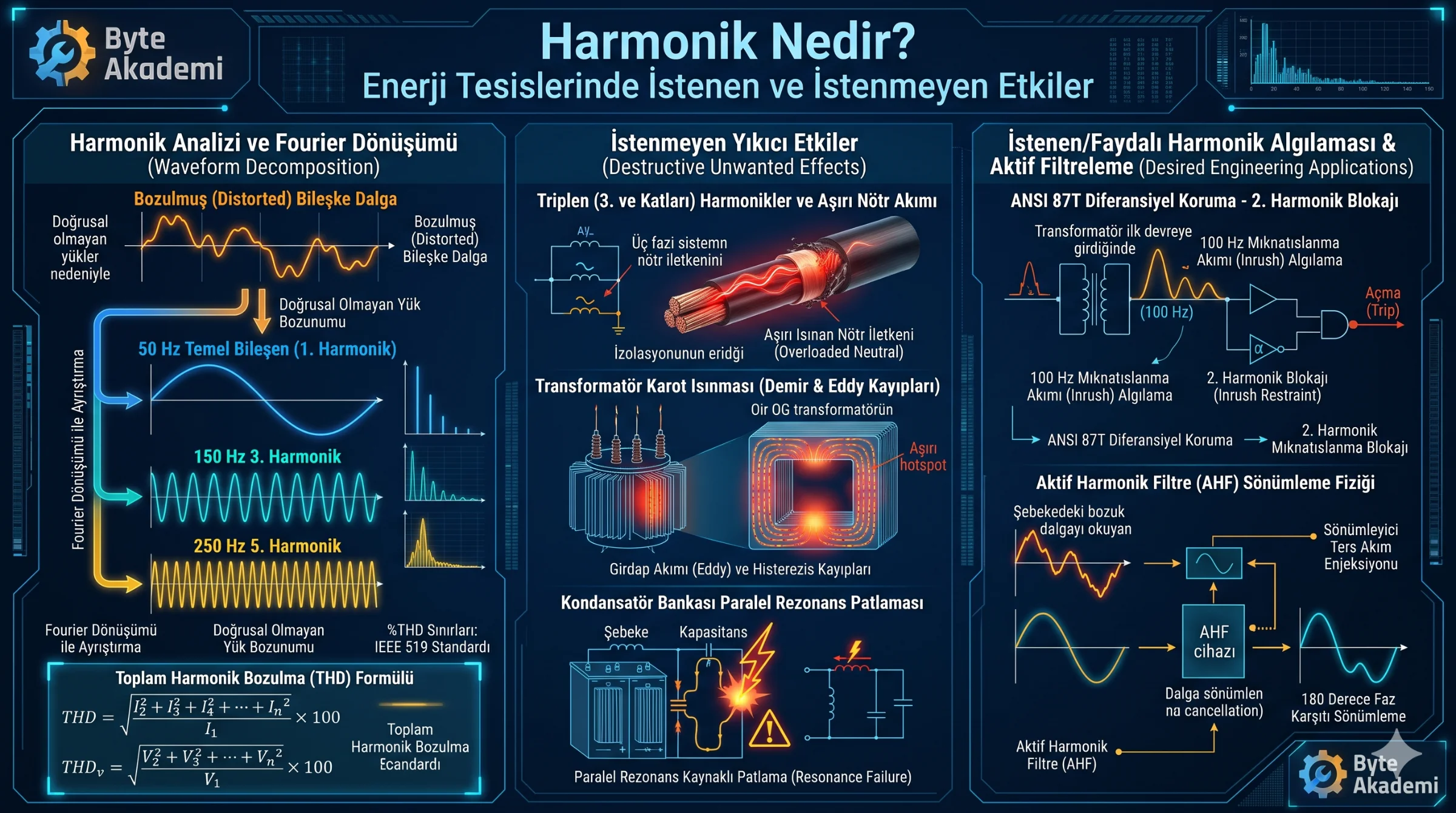
Fourier analysis proves that any periodic non-sinusoidal waveform can be mathematically resolved into a series of pure sinusoids comprising the fundamental power frequency and its integer multiples:
- Fundamental Component (1st Harmonic): 50 Hz or 60 Hz (useful active power transfer)
- 3rd Harmonic (Triplen): 150 Hz (zero-sequence phase accumulation)
- 5th Harmonic: 250 Hz (negative-sequence counter-rotating magnetic field)
- 7th Harmonic: 350 Hz (positive-sequence forward rotor distortion)
  [FOURIER DECOMPOSITION: THE HARMONIC SPECTRUM]

  Distorted Current = [50 Hz Fundamental] + [150 Hz (3rd)] + [250 Hz (5th)] + [350 Hz (7th)]
  Total Harmonic Distortion: THD = sqrt( sum(I_n^2) ) / I_1 * 100%
Harmonics are not merely destructive power quality distortions; when decoded correctly, 2nd harmonics provide the critical mathematical signature that prevents differential relays from tripping during transformer energization.
2. Destructive Harmonics: Four Major Industrial Hazards
When unmitigated, harmonic currents induce severe thermal and dielectric stresses throughout distribution assets:
- Neutral Conductor Burnout (Triplen Harmonics): In balanced three-phase systems, fundamental 50 Hz currents cancel at the neutral star point. However, odd multiples of the 3rd harmonic (3rd, 9th, 15th) are co-phasal (zero-sequence). Instead of canceling, triplen currents add up arithmetically in the neutral conductor, causing neutral currents to reach up to 1.73 times the phase current and inducing electrical fire risks in un-derated cables.
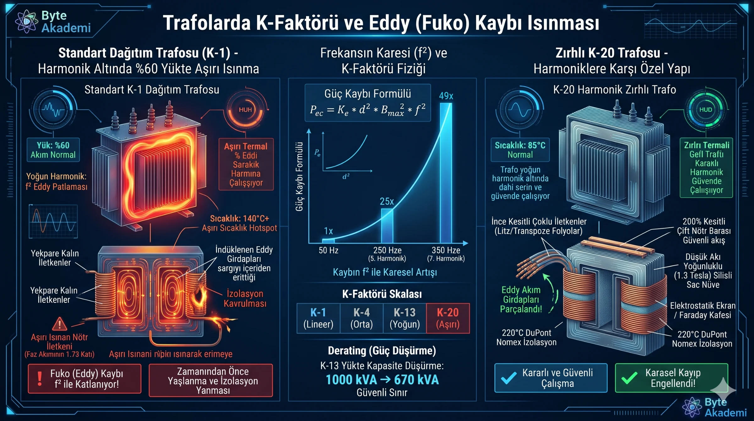
- Eddy Current Losses in Transformers: Stray eddy current dissipation in magnetic cores scales quadratically with frequency (f2). Distorted currents induce extreme localized winding hotspots, demanding specialized K-factor rated transformers (K-13, K-20).
- Parallel Resonance & Capacitor Failures: Power factor correction capacitors exhibit capacitive reactance that decreases inversely with frequency (X_c = 1 / 2*pi*f*C). When network inductive reactance matches capacitor bank reactance at a dominant harmonic frequency (e.g., 5th harmonic), parallel resonance occurs, amplifying harmonic currents to catastrophic levels that rupture capacitor cans.
- Negative Sequence Motor Braking: 5th harmonics induce counter-rotating air-gap fluxes that oppose physical shaft rotation. This parasitic braking torque increases mechanical vibration, elevates operating temperatures, and damages rotor bearings.
3. Desired Harmonics: 2nd Harmonic Inrush Restraint
Harmonics serve a pivotal diagnostic purpose during high-voltage transformer energization. Initial core magnetization forces iron cores into deep saturation, drawing a massive Magnetizing Inrush Current reaching 8 to 12 times rated full-load current. To legacy overcurrent instrumentation, inrush resembles an un-cleared internal transformer short circuit.
Differential protection relays (ANSI 87T) resolve this via harmonic spectral analysis: Internal short circuits generate minimal 2nd harmonics, whereas magnetizing inrush contains a distinctive 15% to 20% 2nd harmonic (100 Hz / 120 Hz) profile.
  [ANSI 87T DIFFERENTIAL RELAY HARMONIC RESTRAINT LOGIC]

  Measured Inflow Surge:
  ├─ If 2nd Harmonic (100 Hz) Content > 15%:
  │  ==> DIAGNOSIS: Benign core magnetization inrush.
  │  ==> ACTION: Engage 2nd Harmonic Restraint! Inhibit trip commands.
  │
  └─ If 2nd Harmonic (100 Hz) Content < 15%:
     ==> DIAGNOSIS: Genuine internal winding flashover.
     ==> ACTION: Execute instantaneous trip! Isolate within milliseconds.
4. Mitigation: Passive LC Traps vs. Active Harmonic Filters (AHF)
Industrial facilities utilize two primary topologies to restore waveform purity:
| Parameter | Passive Harmonic Filter (Tuned LC) | Active Harmonic Filter (AHF / APF) |
|---|---|---|
| Operating Topology | Series inductor-capacitor circuit tuned to bypass a single frequency to earth ground. | IGBT-based power inverter injecting 180-degree phase-inverted counter-currents. |
| Spectral Range | Fixed to discrete design frequencies (e.g., 5th or 7th only). | Dynamic cancellation across the 2nd to 50th harmonic order concurrently. |
| Network Resonance | Susceptible to shifting upstream grid impedance resonance. | Immune to resonance; automatically enforces current-limiting envelopes. |
Active Harmonic Filters operate like Active Noise Canceling (ANC) headphones. Sensors sample distorted current profiles via precision current transformers, process the signal via digital signal processors (DSPs), and command IGBT switches to inject equal and opposite current vectors, leaving the upstream utility seeing only an ideal 50/60 Hz sine wave.