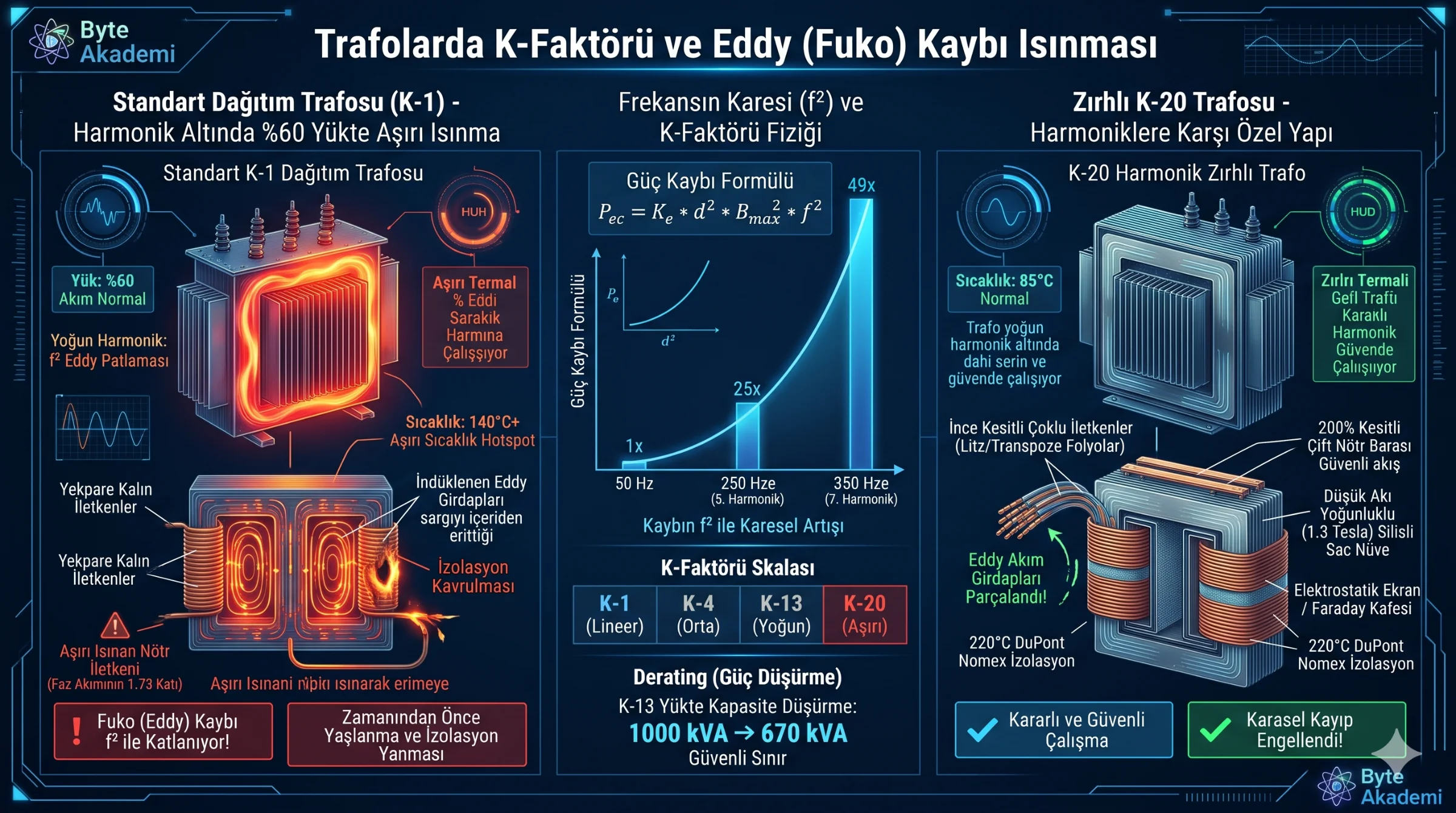
Inspect a modern datacenter substation or mission-critical industrial facility under load: secondary current monitors read well below 60% of the transformer's nominal nameplate rating. Conventional wisdom suggests normal, un-stressed operation. Yet aim a calibrated thermal imager at the dry-type core and windings, and you witness a catastrophic anomaly: core temperatures exceeding 140°C, scorched epoxy resin, and deteriorating dielectric varnishes on the verge of breakdown.
How does a transformer operating at half its nominal current rating undergo severe internal thermal destruction? The root cause is not classical resistive heating (I²R), but micro-scale magnetic dissipation governed by Winding Eddy Current Losses (P_ec). Non-linear loads injecting 250 Hz and 350 Hz harmonic currents turn standard distribution units into internal induction furnaces. Preventing this failure requires engineering the magnetic core and copper architecture around the K-Factor metric. This deep dive examines the physics of quadratic frequency losses, laminated foil topologies, and the engineering principles behind K-13 and K-20 standards.
1. Why Eddy Current Losses Scale Quadratically (f²)
Total transformer losses comprise no-load core losses (hysteresis and core eddy currents) and load-dependent winding losses. Winding losses consist of fundamental ohmic resistance plus stray Winding Eddy Losses (P_ec) induced by leakage flux cutting across conductor cross-sections.
Derived from Maxwell-Faraday induction laws, stray eddy loss within a conducting medium is expressed by:
P_ec = K_e * d^2 * B_max^2 * f^2Where d represents conductor lamination thickness, B_max denotes peak magnetic flux density, and f represents the electrical frequency. The decisive variable is the squared frequency exponent (²):
- At 50/60 Hz Fundamental: Stray eddy dissipation remains bounded within standard design margins (~5% to 10% of ohmic losses).
- With 5th Harmonic (250 Hz) Current: While frequency scales 5-fold, winding eddy losses surge by 5²—an immediate 25-fold increase!
- Adding 7th Harmonic (350 Hz) Current: Eddy dissipation surges by 7²—a 49-fold thermal escalation!
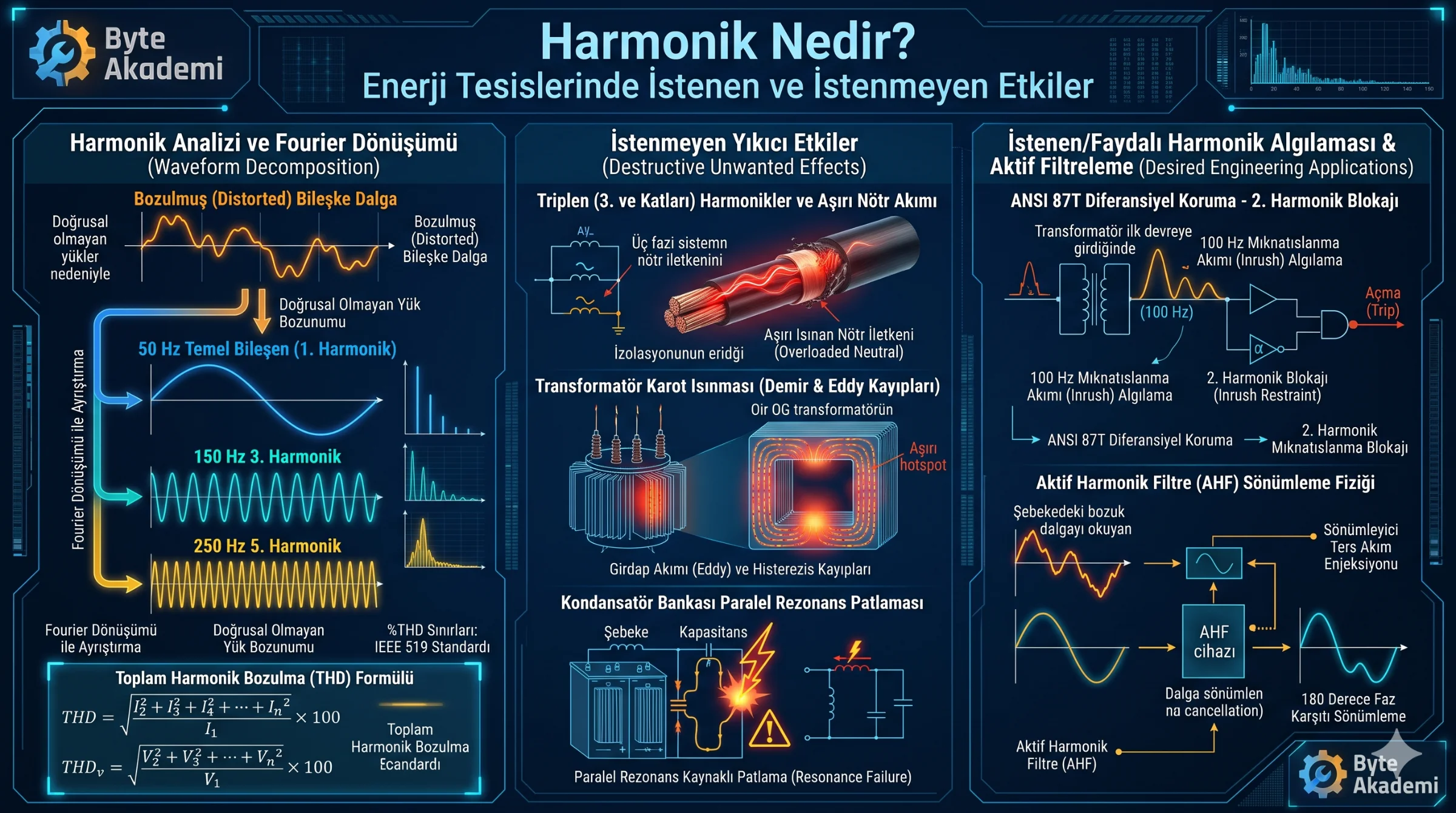
Standard Class-1 distribution transformers assume low harmonic distortion. When non-linear server power supplies, variable speed drives, and battery inverters draw distorted currents, localized internal hot-spots burn out conventional Class F dielectric insulation despite modest primary current draws.
In the presence of high-order harmonics, standard transformers do not fail from simple resistive overcurrent; they self-destruct from quadratic eddy current vortices circulating within the copper windings.
2. Deconstructing the K-Factor: IEEE C57.110 Mathematical Shield
To quantify transformer withstand capabilities against harmonic heating, the ANSI/IEEE C57.110 standard established the K-Factor. The K-factor represents the ratio of total winding eddy losses under distorted conditions relative to pure sinusoidal operation:
K = Sum [ I_h^2 * h^2 ] / Sum [ I_h^2 ]Where h represents the harmonic order (1st, 3rd, 5th, 7th...) and I_h is the normalized per-unit RMS current of that harmonic. For an ideal sinusoidal utility supply with zero distortion (h=1), K = 1. Standard utility transformers carry a baseline K-1 rating.
  [APPLICATION SPECTRUM & K-FACTOR SELECTION GUIDE]

  K-Rating   Typical Non-Linear Load Profiles                          Thermal Severity
  ---------  --------------------------------------------------------  ---------------------------------------
  K-1        Resistive heaters, standard induction motors, incandescence Pure Sinusoidal (No Harmonics)
  K-4        Welders, induction heaters, fluorescent electronic ballasts Moderate Harmonic Profile
  K-13       Telecom facilities, multi-phase UPS systems, medical imaging Severe Non-Linear Loading
  K-20       Hyperscale datacenters, high-density AI server clusters    Extreme Harmonic Stress Zone
  K-30       Industrial arc furnaces, large thyristor-controlled drives Critical Maximum Thermal Design
3. Anatomy of a K-Factor Rated Transformer
A true K-rated transformer is fundamentally redesigned from the core outwards to handle high-frequency stray flux:
- Parallel Laminated Strips & Transposed Litz Conductors: Massive solid copper busbars are replaced by transposed, thin insulated ribbons. Reducing individual conductor thickness (d) directly suppresses the physical area available for circulating eddy loops.
- 200% Rated Neutral Assembly: Triplen harmonics (3rd, 9th, 15th) are additive in the neutral conductor. To prevent neutral terminal flashover, secondary neutral lugs and busbars are engineered with double the cross-sectional copper area (200%) of the main phase conductors.
- Flux Derated Silicon Cores: To eliminate core saturation under harmonic voltage distortion, magnetic cores employ high-grade, laser-scribed grain-oriented silicon steel operating at conservative flux densities (1.3 to 1.4 Tesla vs. conventional 1.7 Tesla).
- Electrostatic Faraday Shielding: A grounded continuous copper barrier between primary and secondary windings attenuates high-frequency common-mode noise and capacitive harmonic coupling.
4. Transformer Derating Methodology for Non-K Units
When operating a standard K-1 unit under elevated harmonic profiles, the transformer must undergo strict mathematical derating to avoid catastrophic thermal runaway. The maximum permissible continuous loading factor (q) is calculated via IEEE C57.110:
Permissible Load Factor = Rated kVA * sqrt( 1 / (1 + (P_ec-pu * (K - 1))) )For a standard 1,000 kVA transformer with a baseline 10% per-unit eddy loss (P_ec-pu = 0.1) subjected to a K-13 server load, its safe operating capacity collapses to approximately 670 kVA. Operating beyond this derated ceiling forces internal hot-spots beyond 180°C, triggering irreversible dielectric breakdown.
Harmonics turn nominal current ratings into unreliable indicators of thermal health. In mission-critical power distribution, specifying K-13 or K-20 rated transformers provides essential mechanical defenses against the destructive quadratic heating physics of non-linear loads.