Hello there, fellow power systems engineer! If a vacuum circuit breaker fails in a substation, you can swap the truck in an hour; if an XLPE cable termination flashes over, a jointer can rebuild it in a shift. But if a 2.5 MVA or 50 MVA Power Transformer suffers an un-cleared internal winding fault, replacement lead times stretch across months and cost hundreds of thousands of dollars!
Even worse, incipient transformer faults are silent killers. While the transformer hums peacefully at 50/60 Hz on the outside, deep inside the mineral oil tank, inter-turn paper insulation may be carbonizing or micro-arcs may be cracking hydrocarbon molecules apart. Standing between a minor internal fault and a catastrophic tank rupture are two legendary guardians: the hydro-mechanical Buchholz Relay (ANSI 63) and the high-speed digital Transformer Differential Relay (ANSI 87T). Grab a coffee, and let's dive into the fluid mechanics, IEC 60599 Dissolved Gas Analysis (DGA) chemistry, and Dyn11 vector matrices that keep power transformers alive!
1. The Buchholz Relay (ANSI 63): Fluid Mechanics & Dual-Stage Gas Detection
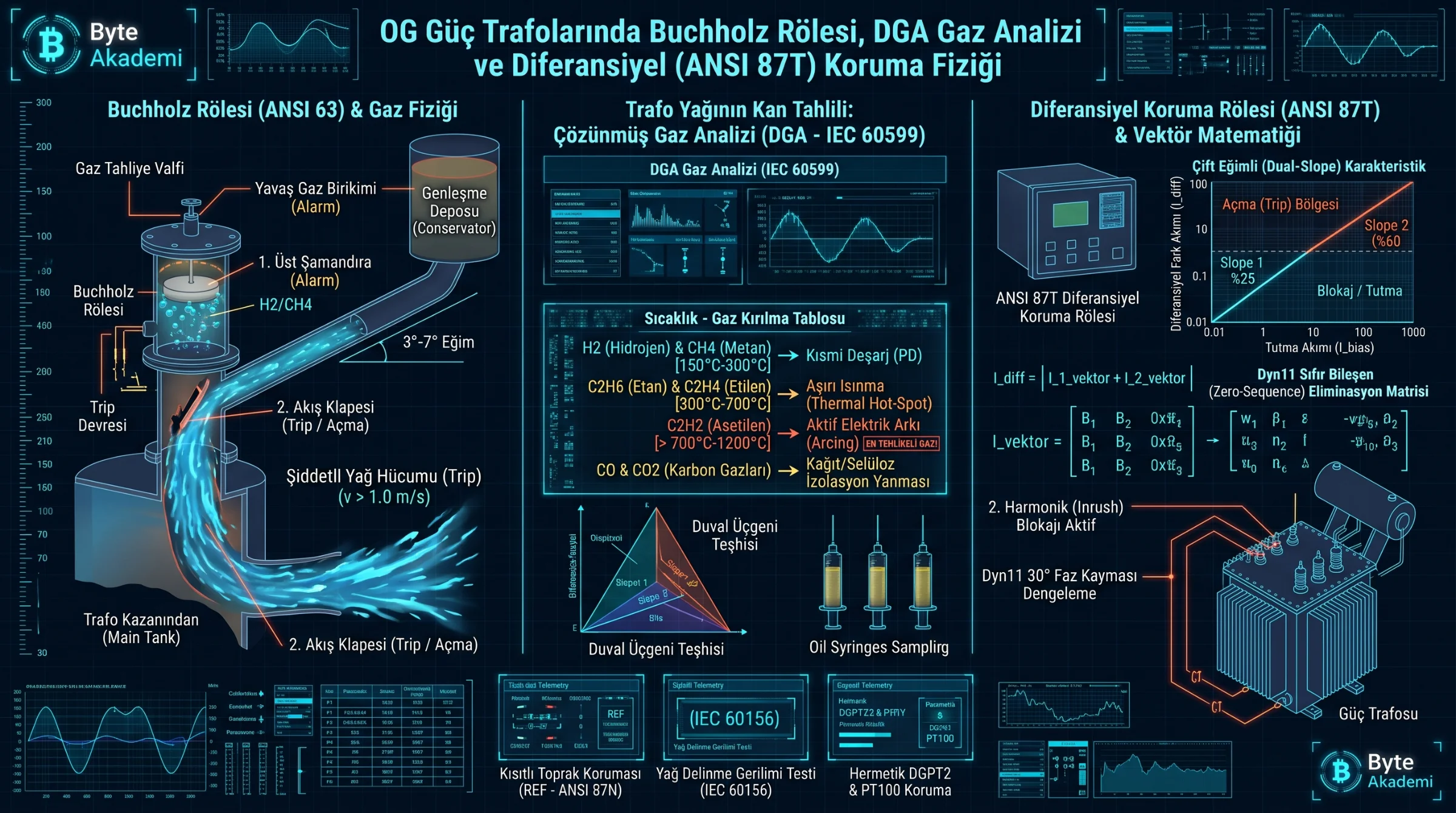
Mounted inside the inclined pipe (installed at a strict 3° to 7° upward slope) connecting the main transformer tank to the overhead conservator drum, the Buchholz Relay operates purely on Archimedes buoyancy and hydrodynamic oil momentum:
- Upper Float (Alarm Stage — Slow Gas Accumulation): During low-energy incipient faults—such as core bolt overheating, stray flux hotspots, or partial discharge—decomposing insulating oil releases gas bubbles (H2, CH4) that migrate up the sloped pipe and become trapped at the top of the Buchholz chamber. As gas displaces the oil downward, the Upper Float drops and closes a magnetic reed switch, triggering a control room ALARM before catastrophic breakdown occurs.
- Lower Surge Flap (Trip Stage — Violent Oil Surge): During a high-energy phase-to-phase or inter-turn short circuit, the electric arc vaporizes surrounding oil instantaneously, launching a high-velocity pressure wave (> 1.0 to 1.5 m/s) rushing toward the conservator. This oil surge slams against the Lower Surge Vane (Flap), immediately tripping both primary and secondary circuit breakers within milliseconds.
  [BUCHHOLZ RELAY HYDRO-MECHANICAL ARCHITECTURE (3° - 7° PIPE SLOPE)]

                    (Upward Pipe Toward Conservator Tank: 3°-7° Tilt)
                                         ^
                                        / /
  +------------------------------------/ /----+
  | [Gas Sampling Petcock] (Trapped H2 / C2H2)|
  |  ~~~~~~~ ~~~~~~~ ~~~~~~~ ~~~~~~~ ~~~~~~~  | <-- Oil Level Displaced Downward
  |     ( O ) <-- 1. UPPER FLOAT (ALARM!)     |     (Incipient Hot-Spot / PD)
  |                                           |
  |             |  /                          |
  |  =========  | / <-- 2. SURGE FLAP (TRIP!) | <-- Violent Oil Surge (v > 1.0 m/s)
  |  Oil Surge  |/      (Instant Breaker Trip)|     (Internal Winding Arc Fault)
  +-------------------------------------------+
         ^
/ / (From Main Transformer Tank)When a Buchholz Alarm triggers, never blindly open the top petcock to bleed off the gas into the air! That trapped gas is forensic evidence: colorless non-flammable gas indicates harmless trapped air after oil filling; yellowish gas points to burning cellulose paper (CO/CO2); and dark grey, highly flammable gas proves active internal arcing (Acetylene).
Re-energizing a power transformer after a Buchholz surge trip or an ANSI 87T differential trip without running Dissolved Gas Analysis is the fastest way to turn a repairable winding fault into a catastrophic tank explosion.
2. Transformer "Blood Work": Dissolved Gas Analysis (DGA — IEC 60599)
As mineral oil hydrocarbons and cellulose Kraft paper experience thermal and electrical stress, chemical bonds fracture at predictable temperature thresholds:
| Key Fault Gas | Formation Temperature | Internal Transformer Fault Diagnosis (IEC 60599) |
|---|---|---|
| Hydrogen (H2) & Methane (CH4) | 150 °C – 300 °C | Corona / Partial Discharge (PD) inside micro-voids or moisture bubbles. |
| Ethane (C2H6) & Ethylene (C2H4) | 300 °C – 700 °C | Thermal Overheating: Circulating core currents, loose OLTC contacts, or blocked cooling ducts. |
| Acetylene (C2H2) — CRITICAL! | > 700 °C – 1200 °C | High-Energy Arcing: Triple carbon bonds only form inside electric arcs. Even > 5 ppm demands immediate action! |
| CO & Carbon Dioxide (CO2) | > 120 °C (Cellulose) | Solid Paper Insulation Degradation: Direct thermal breakdown of winding turn insulation. |
3. Digital Differential Protection (ANSI 87T): Dyn11 Phase Shift & Dual-Slope Restraint
To clear severe internal faults in under 20 milliseconds, transformers rated 5 MVA and above rely on ANSI 87T Percentage Differential Relays. To prevent false tripping during external through-faults or energization, digital 87T relays solve three mathematical challenges:
- Dyn11 Vector Group Phase Shift (30°) & Zero-Sequence Filtering: Across a Delta-Wye (Dyn11) transformer, secondary currents lead primary currents by 30 degrees, and external ground faults on the Wye side circulate zero-sequence current (I0) that never appears on the Delta line CTs. The 87T microprocessor applies an internal phase-compensation and zero-sequence elimination matrix.
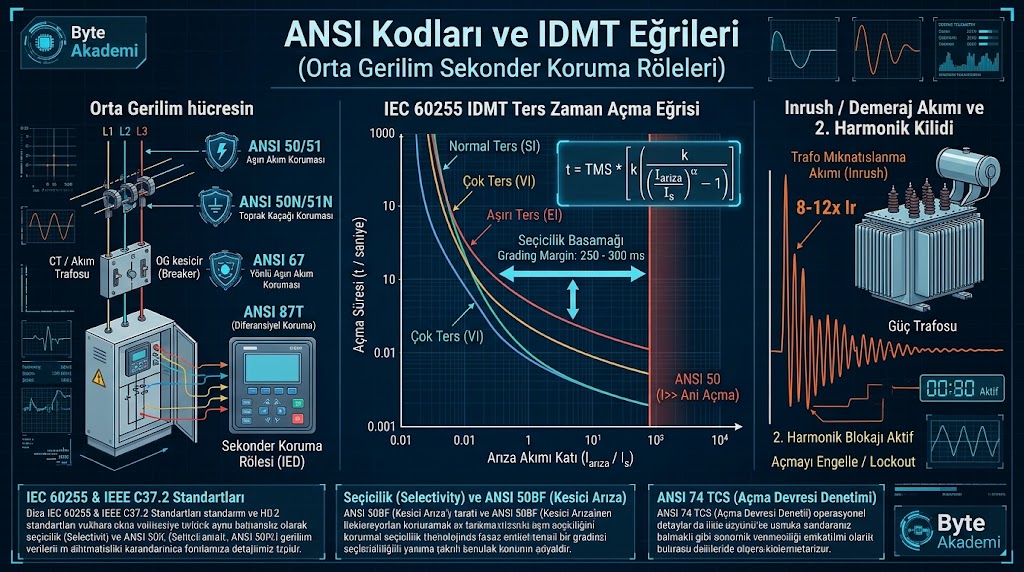
- Dual-Slope Percentage Bias (Restraint): On-Load Tap Changers (OLTC) alter turn ratios by ±10%, and heavy external faults cause asymmetric CT saturation. Slope 1 (20%–30%) accommodates normal OLTC mismatch, while Slope 2 (50%–70%) prevents false trips during severe external CT saturation.
- 2nd Harmonic (Inrush) & 5th Harmonic (Overfluxing) Blocking: Blocks false differential tripping during initial magnetizing inrush when I2f / I1f > 15%.
// ANSI 87T DIFFERENTIAL PROTECTION & ZERO-SEQUENCE FILTER EQUATIONS

// 1. Differential Operating Current vs. Restraint (Bias) Current:
I_diff = | I_1_phasor + I_2_phasor |
I_bias = ( | I_1_phasor | + | I_2_phasor | ) / 2

// 2. Dual-Slope Trip Threshold Criteria:
Slope 1 Region (Normal Load / OLTC) : I_diff > 0.25 * I_bias
Slope 2 Region (CT Saturation Zone) : I_diff > 0.60 * I_bias

// 3. Zero-Sequence Elimination Matrix Applied to Wye-Side CTs:
[ I_A_filtered ]     1   [  2  -1  -1 ]   [ I_A ]
[ I_B_filtered ]  = ---  [ -1   2  -1 ] * [ I_B ]
[ I_C_filtered ] 3 [ -1 -1 2 ] [ I_C ]1. Add Restricted Earth Fault (ANSI 87N / REF) for Winding Neutral Faults: Standard 87T relays lose sensitivity for ground faults occurring near the star-point neutral of a Wye winding (where fault voltage approaches zero). Pairing 87T with ANSI 87N (REF) protects up to 98% of the winding against ground faults.
2. Hermetically Sealed vs. Dry-Type Transformers: Sealed oil transformers without conservators use a DGPT2 (Gas, Pressure, and Temperature) relay, whereas Cast-Resin Dry-Type transformers use PT100 RTD probes with an ANSI 49T thermal relay.
3. Annual Oil Breakdown Voltage (BDV) Check: Per IEC 60156, 34.5 kV transformer oil dielectric strength across a 2.5 mm gap should exceed 60 kV when new and never drop below 40 kV in service.