1. The Sensory Organs of MV Switchgear: Scaling 36,000 Volts and 25,000 Amps for Digital Relays
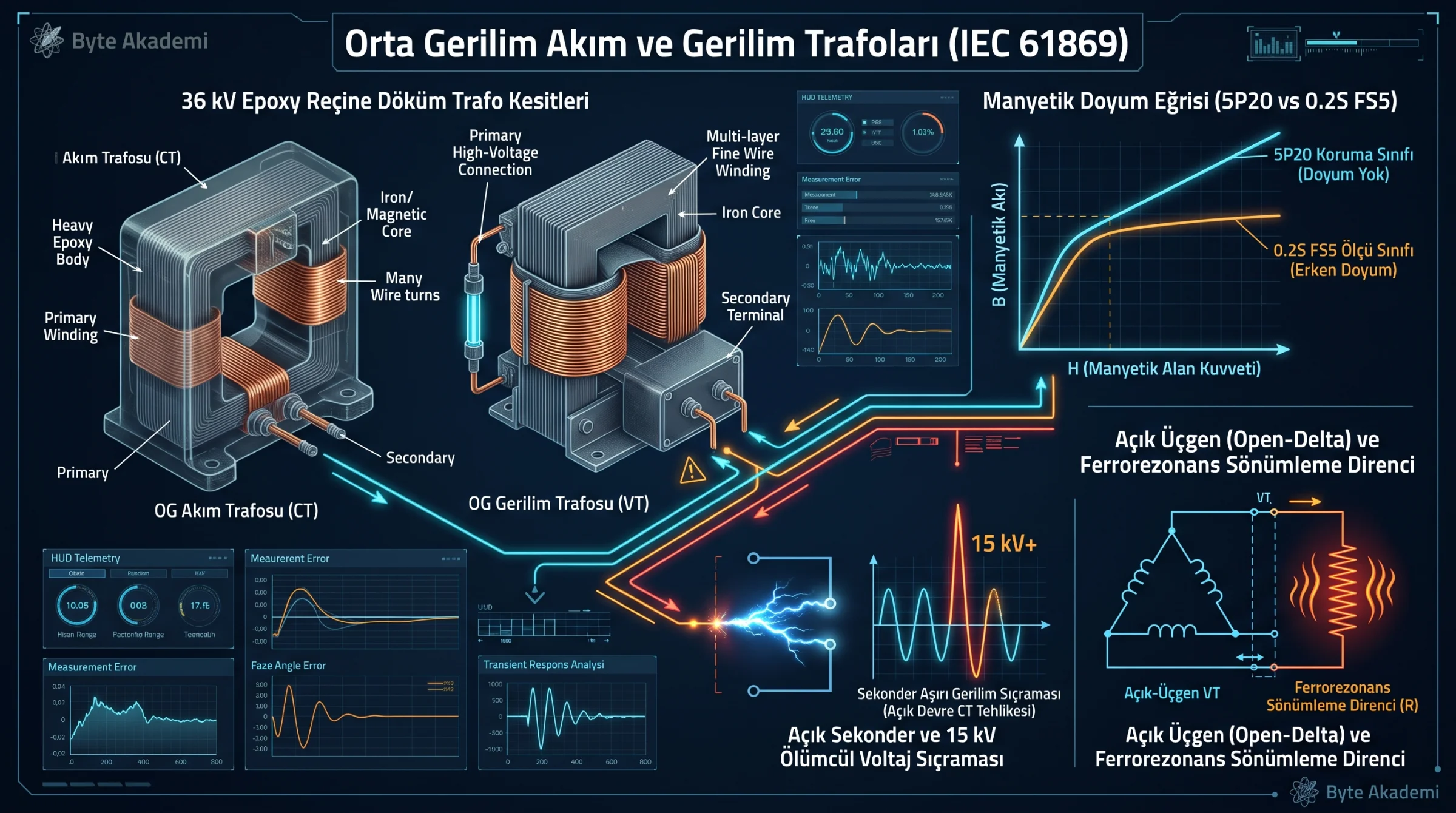
Inside a Medium Voltage (1 kV – 36 kV) switchgear bay, microprocessor-based Intelligent Electronic Devices (IEDs / protection relays) and revenue meters cannot interface directly with 34.5 kV primary busbars or 25 kA short-circuit fault currents. Epoxy-resin cast Instrument Transformers—Current Transformers (CTs) and Voltage Transformers (VTs/PTs)—provide galvanic isolation while scaling primary values down to standardized secondary signals (1A / 5A and 100V / √3 or 110V / √3).
Governed by IEC 61869-2 (Current Transformers) and IEC 61869-3 (Inductive Voltage Transformers), these two components operate under completely opposite electromagnetic boundary conditions:
- Current Transformer (CT): Connected in SERIES with the primary power conductor. Its primary winding consists of a single bar or a few heavy turns, while the secondary has hundreds of fine turns. Under normal service, a CT operates into the near-zero impedance of relay current coils—effectively in a continuous short-circuit state.
- Voltage / Potential Transformer (VT / PT): Connected in PARALLEL (shunt) between phase and earth (or phase-to-phase). Its primary consists of thousands of high-voltage turns. Under normal service, a VT feeds high-impedance voltage inputs—operating in a near open-circuit state.
During commissioning and relay testing, reversing these two rules triggers catastrophic failure. Opening the secondary circuit (S1–S2) of an energized CT induces multi-kilovolt lethal voltage spikes and explosive core overheating; short-circuiting the secondary terminals (a–n) of a live VT causes immediate thermal burnout.
Opening the secondary terminal of an energized Current Transformer strips away counter-magnetomotive force, driving the iron core into deep saturation and inducing lethal 15,000-Volt zero-crossing spikes.
2. Electromagnetic Physics: Why Does an Open-Circuited CT Explode?
During normal closed-loop operation, primary load current (I1) establishes a powerful primary magnetomotive force (N1 · I1). By Lenz's Law, the induced secondary current (I2) circulates through the connected relay burden and generates an opposing counter-magnetomotive force (N2 · I2) shifted by nearly 180 degrees. The two opposing fields cancel each other out, leaving only a tiny net excitation flux (Φm) in the silicon-steel core.
What happens physically if a technician accidentally disconnects a secondary terminal block while 400 Amps of primary load current is flowing (making I2 = 0)?
- Collapse of Counter-MMF: With I2 = 0, the demagnetizing counter-flux vanishes instantly. All 400 Amps of primary current now act purely as magnetizing excitation current (Im = I1).
- Extreme Core Saturation: Driven by hundreds of times its rated excitation force, the magnetic core slams into deep saturation. Instead of a smooth sine wave, core magnetic flux (Φ) flattens into a clipped trapezoidal wave that only changes polarity during the brief AC current zero-crossings.
- Faraday's Law & Lethal Voltage Spikes: According to Faraday's Law of Induction (e2 = -N2 · dΦ/dt), secondary voltage is proportional to the rate of change of magnetic flux. As the saturated flux snaps from +Φsat to -Φsat across a few microseconds at each zero-crossing, dΦ/dt skyrockets—inducing razor-sharp voltage spikes reaching 3,000 V to 15,000 V across the open secondary terminals!
- Dielectric Flashover & Thermal Rupture: These kilovolt spikes flash over terminal blocks and electrocute personnel, while massive eddy-current and hysteresis core losses bake the epoxy insulation until the CT violently ruptures.
// CURRENT TRANSFORMER MMF BALANCE & OPEN-SECONDARY SPIKE PHYSICS
// 1. Normal Closed-Loop Operation (Secondary Shorted Through Relay Burden):
N_1 * I_1 - N_2 * I_2 = N_1 * I_m  (I_m ~ 1%, Net Core Flux Phi is Minimal -> V_2 < 5V)

// 2. Open-Circuit Secondary Fault (I_2 = 0):
N_1 * I_1 - 0 = N_1 * I_m          (100% of Primary Current Drives Core Saturation!)

// 3. Peak Induced Secondary Voltage at Current Zero-Crossing (Faraday's Law):
V_peak_open = - N_2 * ( dPhi_sat / dt_zero_crossing )  --> 5,000 V to 15,000 V Spikes!

N_1, N_2 : Primary and Secondary Turn Counts (e.g., N_1 = 1, N_2 = 400)
Phi_sat  : Saturated Core Magnetic Flux (Webers)
dPhi/dt  : Rate of Flux Reversal at Zero-Crossing (Wb/s)
[CT CORE FLUX WAVEFORM vs. LETHAL OPEN-SECONDARY VOLTAGE SPIKES]
Magnetic Flux (Phi) & Secondary Voltage (V2)
+10 kV | | | <-- Lethal Voltage Spikes (Max dPhi/dt!)
| | _________ | ______
+Phi | /| / \ /| / \ <-- Clipped Trapezoidal Saturated Flux
0 |--------/-|-/-----------\---/-|-/--------\-------- (Time - ms)
-Phi |_______/ |/ \_/ |/ \_______
| | |
-10 kV | | | (10 kV+ Needle Pulses Every Half-Cycle!)3. Metering Cores (0.2S FS5) vs. Protection Cores (5P20): Dual-Core CT Specification
MV switchgear CTs typically house two or three physically separate magnetic cores cast inside a single epoxy housing. Specifying the wrong core for the wrong device leads to burned meters or failed relay tripping:
- Metering Core (e.g., Class 0.2S or 0.5 FS5): Engineered with high-permeability Nickel-Iron (Mu-metal) to deliver pinpoint accuracy from 1% to 120% of rated current. Crucially, the FS5 (Instrument Security Factor = 5) rating guarantees that the core intentionally saturates above 5× rated current, shielding delicate revenue meters from destructive short-circuit currents.
- Protection Core (e.g., Class 5P20 or 10P20): Built from grain-oriented silicon steel with a high saturation knee-point voltage. In a 5P20 rating, the "20" (ALF — Accuracy Limit Factor) certifies that the core will NOT saturate up to 20× rated primary current, keeping composite error below 5% so overcurrent relays (ANSI 50/51) accurately trip the breaker during severe faults.
| Engineering Parameter | Metering Core (Revenue & SCADA) | Protection Core (Overcurrent Relaying) | Differential / Transient Core |
|---|---|---|---|
| IEC 61869-2 Designation | 0.2 / 0.2S / 0.5 (FS5 or FS10) | 5P10 / 5P20 / 10P20 | Class PX / PXR / TPX |
| Core Alloy Metallurgy | Nickel-Iron (Permalloy / Mu-Metal) | Grain-Oriented Silicon Steel | High-Knee-Point / Air-Gapped Core |
| Behavior Under Fault Current | Saturates Early (Protects Meters) | Remains Linear up to 20× In | Defined by Knee-Point Voltage (Vk) |
| Typical Rated Burden (VA) | 2.5 VA – 5 VA (For Digital IEDs) | 10 VA – 15 VA – 30 VA | Matched to Loop Lead Resistance |
| Connected Secondary Device | Tariff Energy Meter, Power Analyzer | ANSI 50/51, 50N/51N, 67 Protection Relays | ANSI 87T Transformer / 87B Busbar Diff |
4. The Silent Killer of Voltage Transformers: Ferroresonance & Open-Delta Damping Resistors
In isolated-neutral or impedance-earthed MV networks, three single-pole inductive Voltage Transformers connected phase-to-earth (Star/Wye) frequently explode due to Ferroresonance—a non-linear chaotic oscillation between the saturable iron-core inductance (Lm) of the VT and the zero-sequence phase-to-earth capacitance (C0) of MV XLPE cables and busbars.
Triggered by circuit breaker switching, fuse blowing, or intermittent earth faults, core saturation causes Lm to drop abruptly until it matches the capacitive reactance of the switchgear cables (ωLm = 1 / ωC0). Primary magnetizing current surges up to 100× normal levels, thermally destroying the VT within minutes.
The Engineering Cure (Broken-Delta Winding + Damper Resistor): Phase-to-earth VTs are specified with two secondary windings:
- Primary Measurement Winding (100/√3 V — Star Connected): Feeds phase voltage inputs on relays and meters (Class 0.5 / 3P).
- Residual Earth-Fault Winding (100/3 V — Open-Delta / Broken-Delta): The three auxiliary windings (
da–dn) are wired in series to form a broken triangle. Under balanced 3-phase conditions, the vector sum of voltages equals zero (VR + VS + VT = 0 V). Whenever an earth fault or ferroresonance occurs, zero-sequence voltage (3V0 = 100V) appears across the open-delta terminals. Connecting a heavy-duty 22 Ω – 47 Ω (500W – 1000W) Anti-Ferroresonance Damping Resistor across the open delta immediately absorbs the chaotic resonant energy as heat, saving the VTs from destruction.
1. P1–P2 and S1–S2 Polarity Verification: Primary terminal P1 must face the busbar (power source) and P2 must face the outgoing feeder cable. Reversing S1–S2 wiring on directional (ANSI 67) or differential (ANSI 87) schemes causes nuisance tripping on healthy feeders.
2. Single-Point Secondary Earthing: Earth CT and VT secondary circuits at ONE point only (typically S2 and the VT neutral star point inside the panel). Dual earthing creates ground-loop currents during substation faults.
3. Avoid Oversized VA Burdens on Digital Meters: Specifying a legacy 30 VA metering CT for a modern digital meter that consumes only 0.2 VA inflates the actual security factor from FS5 to FS50+, destroying the meter during a fault. Always specify 2.5 VA or 5 VA for digital metering cores.