The Dielectric Standoff Challenge: Why Air Hits Its Limit
In medium voltage (1 kV – 36 kV) power distribution networks and industrial substations, electrical energy is switched, protected, and metered through MV Switchgear panels. The fundamental physical constraint governing switchgear design is the dielectric clearance between Phase-to-Phase and Phase-to-Earth conductors.
At standard atmospheric pressure, dry air exhibits a dielectric breakdown strength of roughly 3 kV/mm (30 kV/cm). However, once humidity, surface pollution, and Lightning Impulse Withstand Voltage (170 kV BIL for 36 kV networks) are factored in, bare conductors require a minimum air clearance of 300 mm to 320 mm. This physical threshold divides medium voltage switchgear into two primary architectures: Air Insulated Switchgear (AIS) and Gas Insulated Switchgear (GIS / RMU).
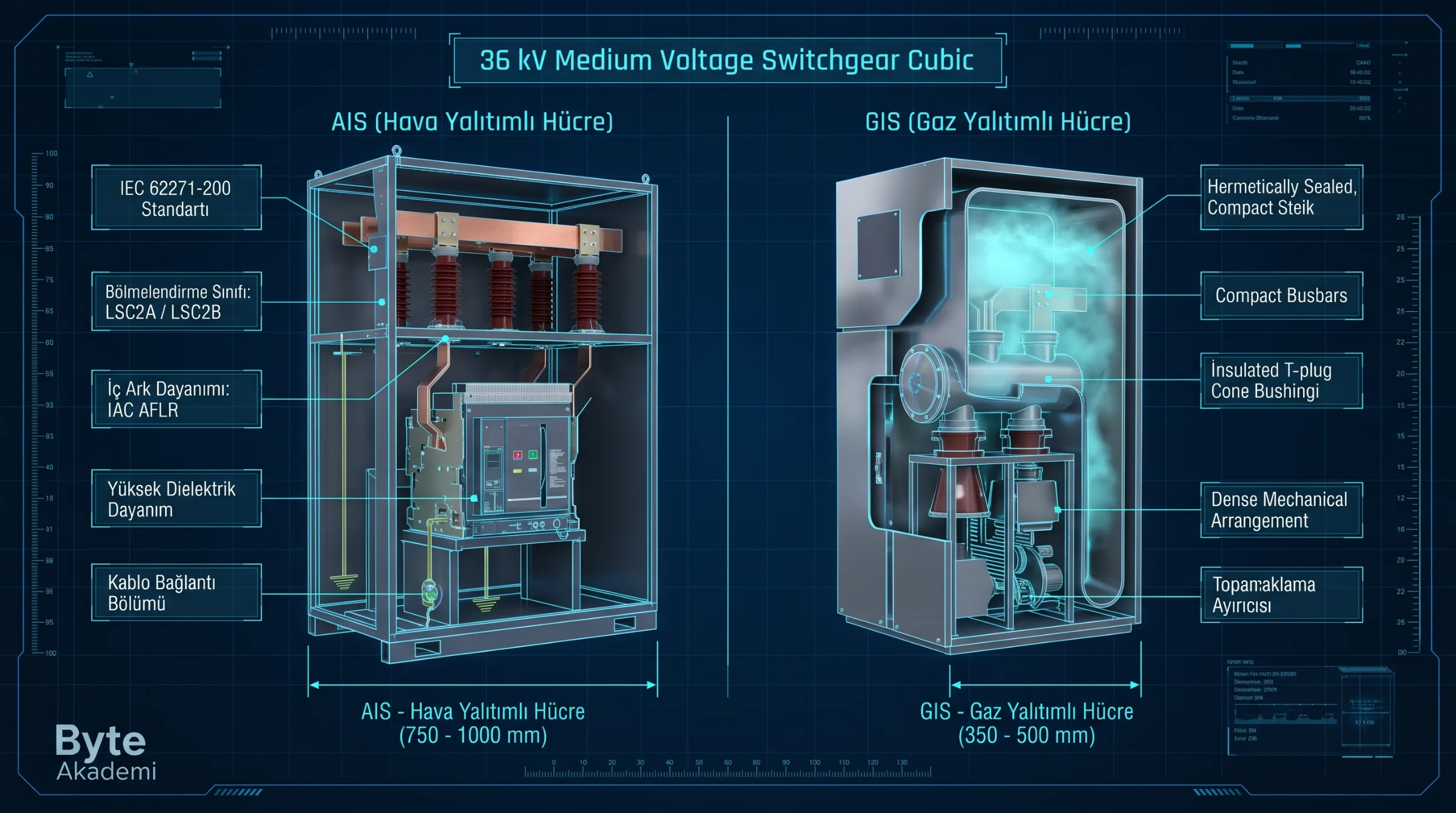
A common field misconception is labeling any cubicle equipped with an SF6 circuit breaker as "GIS." If the main copper busbars, insulators, and cable terminations are exposed to ambient air, the panel is Air Insulated Switchgear (AIS)—regardless of whether the breaker poles use vacuum or SF6 to interrupt the arc. In a true GIS unit, all live busbars and disconnectors are hermetically sealed inside a pressurized stainless-steel vessel filled with SF6 or eco-friendly insulating gas.
1. Air Insulated Switchgear (AIS - Modular & Metal-Clad)
AIS panels rely on ambient air as the primary dielectric medium between live busbars and the earthed enclosure. Depending on the required level of compartmentalization under IEC 62271-200, they are deployed in two main formats:
- Metal-Enclosed (Modular Cubicles): Housed within an earthed metallic shell with partial metallic or insulating partitions. At 36 kV, panel widths typically range from 750 mm to 1000 mm.
- Metal-Clad (Withdrawable Switchgear): Built for critical infrastructure, power plants, and petrochemical facilities. Every primary compartment (busbar, withdrawable circuit breaker truck, cable termination, and LV control) is segregated by earthed metallic barriers.
2. Gas Insulated Switchgear (GIS & Compact RMU)
Sulfur Hexafluoride (SF6) is a strongly electronegative gas that absorbs free electrons, delivering 2.5 to 3 times the dielectric strength of air at atmospheric pressure. By enclosing all primary live parts inside a welded stainless-steel tank pressurized to 1.2 – 1.5 Bar absolute:
- Compact Footprint: While a 36 kV AIS cubicle requires up to 1000 mm of width, a GIS bay achieves the same rating in 350 mm to 500 mm, cutting substation civil construction footprints by up to 60%.
- Complete Environmental Immunity: Because active busbars and three-position disconnectors are hermetically sealed (IP65/IP67 tank), humidity, condensation, coastal salt fog, industrial dust, and rodent intrusion cannot trigger flashovers.
- High-Altitude Performance: Above 1,000 meters elevation, thinner ambient air degrades AIS insulation, requiring derating. Sealed GIS tanks remain completely unaffected at 2,500+ meters in wind and solar power plants.
// PASCHEN'S LAW FOR DIELECTRIC BREAKDOWN VOLTAGE
V_b = (B * p * d) / (ln(A * p * d) - ln(ln(1 + 1/gamma)))

p : Gas Pressure (Bar/Pa)
d : Electrode Gap Distance (mm)
// High electronegativity in SF6 enables vastly smaller gap distances (d)
// without risking dielectric flashover at 170 kV BIL impulse levels.
Decoding IEC 62271-200 Ratings: LSC and IAC
Every compliant MV switchgear nameplate specifies its operational continuity and operator safety boundaries according to IEC 62271-200:
- Loss of Service Continuity (LSC): Defines whether adjacent compartments remain energized during maintenance inside the main cable compartment.
- LSC2A: Busbar and cable/apparatus compartments are segregated, allowing safe access to cable terminations while the main busbar stays live.
- LSC2B: Busbar, switching device (breaker), and cable compartments are physically separated into three independent zones, maintaining full isolation even when cables are disconnected.
- Internal Arc Classification (IAC): Certifies that the cubicle can withstand an internal arc fault (e.g., 16 kA or 25 kA for 1 second) and safely vent 20,000°C plasma gases without injuring personnel.
- IAC AFLR: Verified protection for Authorized personnel (A) standing at the Front (F), Lateral/Sides (L), and Rear (R) of the switchgear.
Technical Comparison: AIS vs. GIS Medium Voltage Switchgear
| Engineering Parameter | AIS (Air Insulated Switchgear) | GIS / RMU (Gas Insulated Switchgear) |
|---|---|---|
| Primary Dielectric Medium | Ambient Atmospheric Air (1 Bar) | Hermetically Sealed SF6 or Dry Air Tank (1.3 Bar) |
| 36 kV Panel Width | 750 mm – 1000 mm | 350 mm – 600 mm (Ultra-Compact) |
| Cable Termination Interface | Conventional Heat/Cold-Shrink Indoor Termination | Screened Plug-in Cone Bushings (EN 50181 Type C) |
| Humidity, Dust & Altitude | Sensitive (Requires Anti-Condensation Heaters & Derating >1000m) | Fully Immune (Sealed IP67 Stainless Steel Vessel) |
| Field Repairability | High (Individual Insulators, CTs, and Switches Replaceable) | Sealed Tank (No Internal Field Maintenance) |
| Initial Capital Cost (CAPEX) | Lower Equipment Cost | 25% – 40% Higher (Offset by Smaller Building Size) |
Screened Plug-In Bushings vs. Open Cable Terminations
GIS switchgear connects to MV cables via EN 50181 outer-cone plug-in bushings (Type A, B, or bolted Type C). Unlike open AIS terminations where dust and moisture accumulation can induce surface tracking and partial discharge, GIS T-connectors are fully screened with an earthed outer semiconductor layer—making the connection safe to touch and resilient against accidental flooding.