Hello there, fellow power systems engineer! Picture this nightmare scenario: it is 3:00 AM, your phone rings, and the night-shift technician tells you that a minor cable fault on an outgoing feeder didn't just trip the local breaker—it bypassed your entire substation and tripped the utility company's main incoming circuit breaker, plunging the whole industrial plant into total darkness! Even if your switchgear is equipped with top-tier vacuum breakers and precision current transformers, a poorly parameterized Protection Relay (IED — Intelligent Electronic Device) turns a localized fault into a facility-wide blackout.
If the circuit breaker is the "muscle" of a Medium Voltage (MV) switchgear bay and the instrument transformers (CTs/VTs) are its "senses," the Secondary Protection Relay is the "Brain." Grab a cup of coffee, and let's decode the exact mathematics behind ANSI device numbers, IEC 60255 IDMT time-current curves, transformer inrush blocking, and selectivity grading like a seasoned commissioning engineer!
1. The Universal Language of Substations: Decoding ANSI / IEEE C37.2 Relay Codes
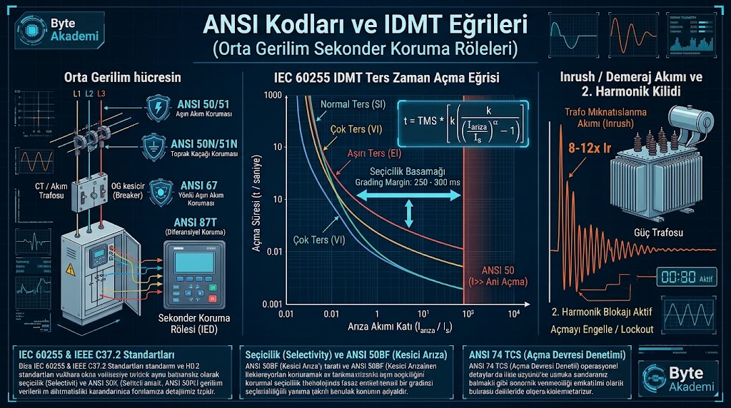
When you open an MV single-line diagram (SLD), every protection function inside a digital IED (whether ABB Relion, Siemens Siprotec, Schneider Sepam/Easergy, or SEL) is identified by standardized ANSI / IEEE C37.2 device numbers:
- ANSI 50 (Instantaneous Phase Overcurrent — I>>): Operates with zero intentional time delay (typically 30 ms to 50 ms). Designed to clear severe high-magnitude phase-to-phase or three-phase short circuits before arc energy destroys busbars or cables.
- ANSI 51 (Time-Delayed Phase Overcurrent — I>): The intelligent workhorse of feeder protection. Uses an inverse time-current characteristic to ride through temporary motor starting surges while tripping on sustained overloads or medium-grade faults.
- ANSI 50N / 51N & 50G / 51G (Earth Fault / Zero-Sequence Protection — I0>): Over 80% of all MV network faults begin as single-phase-to-earth insulation breakdowns! While 50N/51N calculates residual ground current from the vector sum of three phase CTs (IL1 + IL2 + IL3), 50G/51G measures earth leakage directly through a dedicated Core-Balance Toroidal CT, detecting sensitive ground faults down to 1 Amp.
- ANSI 67 / 67N (Directional Overcurrent & Earth Fault): Essential for ring mains, parallel transformers, and plants with solar PV / cogeneration backfeed. Evaluates both current magnitude and the phase angle against busbar VT polarizing voltage to determine whether a fault is upstream or downstream.
- ANSI 87T / 87B (Differential Protection): Compares primary and secondary currents across power transformers (87T) or busbars (87B) using Kirchhoff's current law, tripping within 20 milliseconds on internal faults.
Why do residual 50N relays sometimes nuisance-trip during heavy motor starting or transformer energization? Because slight magnetic saturation differences between the three phase CTs create a "false residual spill current" in the neutral wire. Using an external Toroidal Core-Balance CT (ANSI 50G/51G) around all three XLPE cable cores eliminates CT mismatch errors completely!
While vacuum circuit breakers provide the mechanical muscle of an MV substation, it is the mathematical precision of the protection relay's IDMT curve that isolates a fault in milliseconds without blacking out the entire plant.
2. Inside the Microprocessor: IEC 60255 Inverse Time (IDMT) Equations & Worked Example
Why don't engineers use simple fixed timers for all overcurrent relays? Because under Inverse Definite Minimum Time (IDMT) protection, the higher the fault current, the faster the relay trips! Governed by IEC 60255, digital relays continuously solve this logarithmic equation:
// IEC 60255 INVERSE DEFINITE MINIMUM TIME (IDMT) TRIP EQUATION:

t (seconds) = TMS * [ k / ( ( I_fault / I_s )^alpha - 1 ) ]

// STANDARD IEC CURVE CONSTANTS (k and alpha):
1. Standard Inverse (SI / Normal Inverse) : k = 0.14  | alpha = 0.02
2. Very Inverse (VI)                      : k = 13.5  | alpha = 1.00
3. Extremely Inverse (EI)                 : k = 80.0  | alpha = 2.00
4. Long-Time Inverse (LTI)                : k = 120.0 | alpha = 1.00

t       : Relay Operating (Trip) Time in Seconds
TMS     : Time Multiplier Setting (Dial: typically 0.05 to 1.00)
I_fault : Measured Short-Circuit Fault Current (Amps)
I_s     : Relay Pick-up Current Setting (I> Threshold in Amps)
Worked Substation Calculation (Standard Inverse Curve)
Suppose your 34.5 kV feeder has a 100/5 A CT, a pick-up setting of Is = 100 A, a Time Multiplier Setting of TMS = 0.20, and uses the IEC Standard Inverse (k = 0.14, α = 0.02) curve. A downstream cable fault draws 500 A (which is 5× pick-up: I / Is = 5). How fast does the relay trip?
- Denominator:
5^0.02 - 1 = 1.0327 - 1 = 0.0327 - Trip Time:
t = 0.20 * (0.14 / 0.0327) = 0.20 * 4.28 = 0.856 seconds! - If the fault escalates to 2,000 A (20× pick-up), the exact same curve automatically accelerates the trip time down to 0.44 seconds!
  [IEC 60255 IDMT TIME-CURRENT CURVES & ANSI 50 INSTANTANEOUS CUTOFF]

  Trip Time - t (Seconds)
   10.0 |   \   \
    5.0 |    \   \  <-- Standard Inverse (SI - General MV Feeders)
    2.0 |     \   '--.
    1.0 |      \      '--. <-- Very Inverse (VI - Long High-Impedance Lines)
    0.5 |       '--.      '------.
    0.2 |           '----.        | <-- ANSI 50 (I>> Instantaneous Cutoff: 0.05s!)
   0.05 |                 |_______|____________________________________
        +--------------------------------------------------------------
        1x      2x       5x      10x     15x     20x    (Fault Multiple: I / Is)
        |<-- ANSI 51 (IDMT Region) ------>|<-- ANSI 50 (Instantaneous) -->|
3. Engineering Selection Matrix: Choosing the Right IEC 60255 Curve
| IEC 60255 Curve Type | Constants (k / α) | Mathematical Behavior | Primary MV Substation Application |
|---|---|---|---|
| Standard Inverse (SI) | k = 0.14 | α = 0.02 | Moderate time reduction as fault current increases. | Industrial incomers, general MV ring/radial feeders |
| Very Inverse (VI) | k = 13.5 | α = 1.00 | Steep time reduction where fault current drops along long lines. | Long overhead lines & underground XLPE distribution cables |
| Extremely Inverse (EI) | k = 80.0 | α = 2.00 | Matches I2t thermal heating slopes and HRC fuse curves. | Grading with MV fuses, transformer feeders & heavy pumps |
| Definite Time (DT) | Fixed Delay (e.g., 0.3s) | Constant trip delay regardless of fault current magnitude. | Impedance-earthed 51N ground protection & stage-2 backups |
4. Selectivity Grading Margins & Transformer Inrush (2nd Harmonic) Restraint
Two critical coordination rules separate reliable substations from blackout-prone installations:
- The 250 ms – 300 ms Grading Margin Rule: When coordinating an upstream main breaker with a downstream feeder breaker, maintain a minimum 0.25s to 0.30s time gap between their curves at maximum fault current. This covers downstream vacuum breaker mechanical opening + arc extinction (~60 ms), relay overshoot/reset time (~50 ms), and CT/timing tolerances (~100 ms).
- Magnetizing Inrush & 2nd Harmonic Blocking: Energizing an unloaded power transformer draws a transient magnetizing inrush current reaching 8× to 12× rated current for ~100 ms. To prevent ANSI 50 from nuisance tripping on energization, enable 2nd Harmonic Restraint (typically set at I2f / I1f > 15%) so the relay recognizes the 100 Hz/120 Hz asymmetric waveform signature of transformer core saturation and blocks false tripping.
1. ANSI 74 (Trip Circuit Supervision - TCS): Continuously sends a milliamp monitoring current through the breaker's DC trip coil (both when the breaker is Open and Closed) to alert operators immediately if DC control wiring is broken.
2. ANSI 50BF (Breaker Failure Protection): If a relay sends a trip signal and current fails to drop to zero within 150 ms (due to a jammed breaker mechanism), 50BF issues a backup trip to clear the entire upstream busbar.
3. Always Extract COMTRADE Oscillography Before Resetting: Never clear fault LEDs blindly—download the relay's internal waveform log first to inspect exact fault phase vectors and breaker clearing times.