Hello there, fellow high-voltage engineer! Have you ever experienced that dreaded call a few days after energizing a brand-new 34.5 kV switchgear lineup—where a loud explosion echoes from the cable compartment, tripping the main breaker and filling the substation with the acrid smell of vaporized polyethylene? When you open the panel door, you discover that the heavy XLPE power cable didn't fail underground; it blew apart right at the base of the Cable Termination, precisely where the black semiconductive screen was stripped back!
Industry reliability data confirms that over 75% of all Medium Voltage (MV) cable system failures originate not in the factory-extruded cable body, but inside field-installed Cable Terminations and Joints. While terminating a 400V low-voltage wire only requires stripping PVC and wrapping electrical tape, stripping a 36 kV XLPE cable unleashes an invisible electromagnetic monster: Dielectric Field Stress Concentration. Grab a cup of coffee, and let's dissect the physics of electric field stress control, Partial Discharge (PD) electrical treeing, and the golden rules of MV cable splicing!
1. Anatomy of an MV XLPE Cable: Why Does That Black "Semicon" Layer Exist?
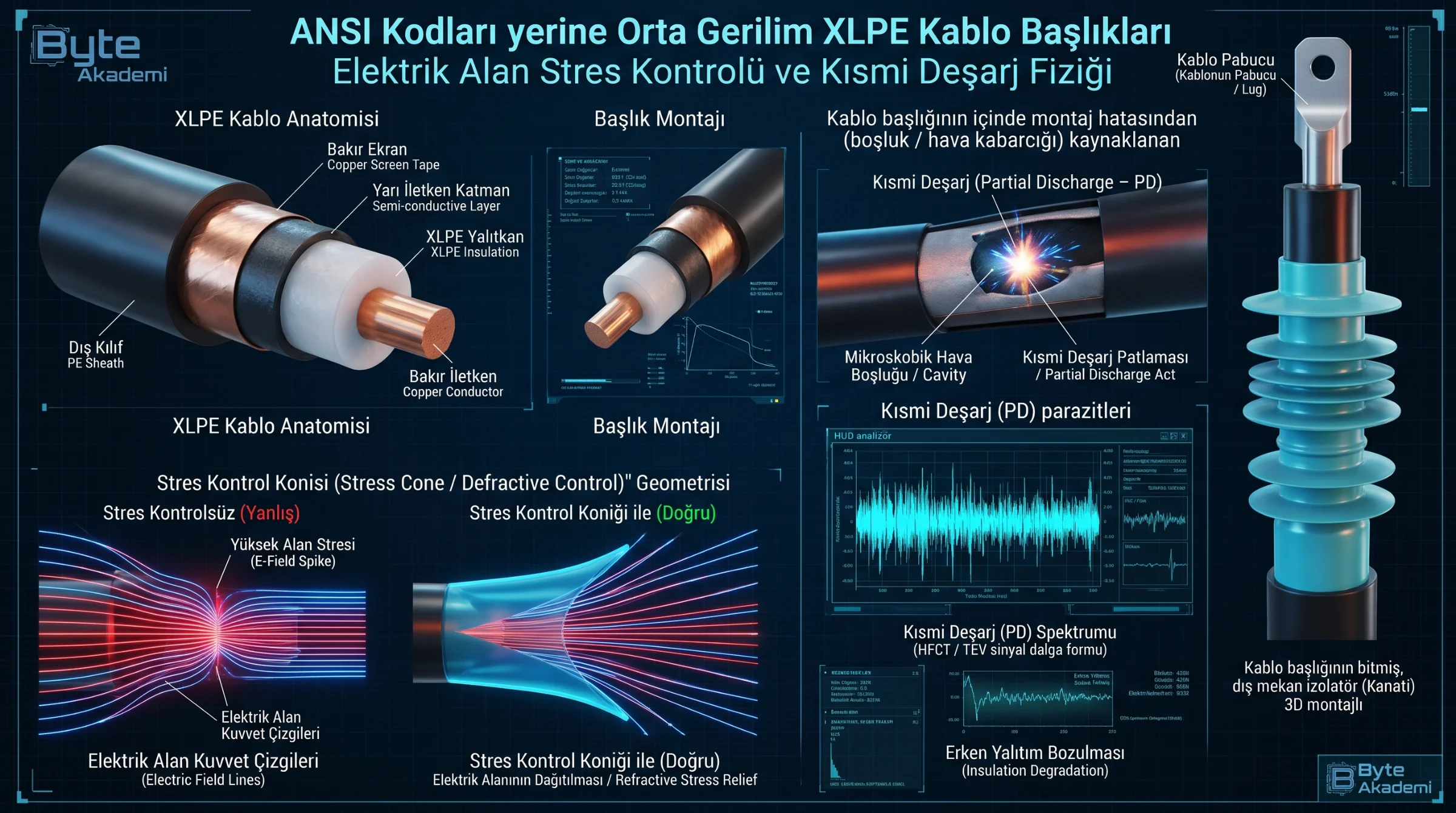
Cross-sectioning a 36 kV XLPE (Cross-Linked Polyethylene) cable reveals six concentric layers engineered to contain kilovolt radial electric fields:
- Stranded Conductor (Copper or Aluminum): Compacted circular strands carrying load current.
- Inner Semiconductive Screen: Extruded carbon-loaded polymer smoothing out the ridges of individual metal strands so electric field lines launch uniformly into the insulation without point-discharge spikes.
- XLPE Primary Insulation: Peroxide or silane cross-linked polyethylene providing high dielectric strength (~20–30 kV/mm) and 90°C continuous thermal rating.
- Outer Semiconductive Screen: Bonds tightly to the outer surface of the XLPE insulation, ensuring zero air gaps between the dielectric and the grounded metallic shield.
- Metallic Screen (Copper Wires / Tape): Carries capacitive charging currents and provides the zero-potential earth reference (Faraday cage) plus earth-fault current return path.
- Outer Sheath (PVC or LSZH/HDPE): Mechanical and moisture barrier.
Untrained installers sometimes mistake the black outer layer on top of the white XLPE for a second layer of insulation. It is Semiconductive! If you fail to strip it back to the specified dimension or leave carbon smudges on the white XLPE surface, you create a direct high-voltage tracking path to ground.
Stripping a 36 kV XLPE cable without a stress control cone forces equipotential field lines to crowd at the semicon cutback edge—exceeding air breakdown strength and triggering destructive Partial Discharge.
2. Why Do Terminations Explode? Electric Field Stress Concentration & Stress Cones
Inside an intact shielded XLPE cable, the electric field between the energized center conductor and the grounded outer semicon is purely radial and uniform. The moment a cable jointer strips back the copper screen and terminates the black Outer Semiconductive Layer, all equipotential electric field lines converge violently onto that razor-thin Semicon Cutback Step!
// RADIAL ELECTRIC FIELD (E) & SEMICON CUTBACK STRESS CONCENTRATION PHYSICS

// 1. Uniform Radial Electric Field Inside Intact XLPE Cable:
E(r) = U_0 / [ r * ln( R_outer / r_inner ) ]     (Nominal Stress: ~3.5 kV/mm)

// 2. Uncontrolled Peak Stress at Semicon Cutback Edge (Without Stress Cone):
E_max_edge = Beta_stress * E_nominal             (Spikes > 25 kV/mm -> AIR IONIZATION!)

// 3. Refracted Field Using High-Permittivity (High-K) Stress Control Tube:
epsilon_r1 * E_XLPE = epsilon_r2 * E_Stress_Tube (epsilon_r2 ~ 28 spreads equipotential lines!)

U_0            : Phase-to-Ground Voltage (e.g., 34.5 kV / sqrt(3) = 20 kV)
r_inner, R_outer: Conductor Radius and Insulation Shield Radius
Beta_stress    : Geometric Sharp-Edge Stress Multiplier (6x to 10x amplification!)
epsilon_r2     : Relative Permittivity of Stress Control Sleeve (~28 vs. XLPE = 2.3)
Because ambient air breaks down at just 3 kV/mm, an unshielded semicon step experiencing 20+ kV/mm immediately ionizes surrounding air molecules—igniting continuous Corona and Partial Discharge (PD) that erodes the XLPE via Electrical Treeing until phase-to-ground flashover occurs.
  [EQUIPOTENTIAL ELECTRIC FIELD LINES AT THE SEMICON CUTBACK STEP]

  A) UNCONTROLLED CUTBACK (NO STRESS CONE):     B) REFRACTED FIELD WITH STRESS CONTROL TUBE:
     (Field Lines Crowd at Edge -> FLASHOVER!)     (High-K Sleeve Spreads Field Smoothly!)

               _.--'      /  /                                    _..---'''''---.._
           _.-'          /  /                                _..-'                 '-.._
  =======+==============+==+======= (XLPE)      =======+================================+==== (XLPE)
  #######| <--[25 kV/mm! Corona & PD Treeing]   #######|================================|==== (Stress Tube)
  (Semicon Edge - Extreme Field Crowding)       (Semicon)       [Smooth Gradient: Stress < 3 kV/mm]
3. Technology Comparison: Heat-Shrink vs. Cold-Shrink vs. GIS Separable Connectors (Elbows)
| Engineering Parameter | Heat-Shrink Termination | Cold-Shrink Termination | GIS Separable Connector (T-Body / Elbow) |
|---|---|---|---|
| Insulation Elastomer | Cross-Linked Polyolefin Tubing | Liquid Silicone Rubber (LSR) or EPDM | Peroxide-Cured EPDM / Silicone with Outer Shield |
| Installation Method | Propane Torch or High-Power Heat Gun | Pulling Out Internal Plastic Spiral Core (No Torch!) | Bolted Plug-In onto EN 50181 Type C Bushing |
| Thermal Breathing Compliance | Moderate (Rigid after cooling) | Superior (Maintains constant radial elastic pressure) | Fully Submersible & Hermetically Sealed (IP68) |
| Workmanship Sensitivity | High (Risk of scorching or uneven shrinking) | Low (Pre-expanded factory tension) | Moderate (Requires exact torque & silicone lubricant) |
| Touch Safety & Clearance | Unshielded (Requires full air clearance) | Unshielded (Requires full air clearance) | Dead-Front Touch-Safe (Grounded outer screen) |
4. Partial Discharge (PD) Triggers & The Golden Toroidal CT Earthing Rule
Even with a premium termination kit, four field errors guarantee premature failure or protection blindness:
- Knife Nicking the XLPE at the Semicon Cut: Scoring the white XLPE by just 0.2 mm traps an air pocket at the highest-stress junction. Because air has a lower permittivity (εr = 1) than XLPE (εr = 2.3), electric stress concentrates inside the air void, firing thousands of picocoulomb (pC) partial discharges per minute.
- Wiping Solvent Toward the Insulation: Always wipe cleaning solvent from the clean white XLPE toward the black semicon—never drag conductive carbon residue onto the bare insulation!
- The Toroidal Core-Balance CT Earthing Rule (ANSI 50G/51G): If the cable passes through a toroidal earth-fault CT at the bottom of the switchgear, the copper screen earthing braid emerging from the termination MUST pass back DOWN through the center of the toroidal CT BEFORE connecting to the earth bar! If you ground the braid above the CT, capacitive and fault return currents cancel out inside the toroid, blinding your earth-fault relay.
  [CRITICAL FIELD RULE: ROUTING CABLE SCREEN BRAID THROUGH A TOROIDAL CT]

        [MV Switchgear Bushing]
               |
            (Lug)
               |
           /=======\  <-- Cable Termination Body
           |       |
           +---+---+
               | \
               |  \  (Copper Screen Earthing Braid)
      =========|===\=========  <-- [TOROIDAL CORE-BALANCE CT (ANSI 50G/51G)]
               |    |
               |   /  (Screen braid MUST pass BACK THROUGH the CT window before earthing!)
               |  /
               | +---> [Switchgear Earth Bar (GND)]
               |
[MV XLPE Power Cable]Never subject service-aged XLPE cables to traditional High-Voltage DC Hipot tests