Submitting an AI query or streaming 4K media creates the illusion of seamless cloud computing. In physical reality, every execution translates into real-world thermodynamic work inside vast infrastructure facilities: megawatts of electrical grid power dissipating as heat, and cooling towers evaporating thousands of liters of freshwater every hour to maintain silicon junctions below critical thermal limits.
How do we quantify the true environmental baseline of computational infrastructure beyond corporate marketing claims? The solution lies within the thermodynamic relationship between Power Usage Effectiveness (PUE) and Water Usage Effectiveness (WUE). This analysis explores facility efficiency metrics, evaporative cooling trade-offs, regional grid dynamics, and a benchmark 100 MW datacenter calculation.
1. Power Usage Effectiveness (PUE) Breakdown
The established global metric for assessing data center electrical efficiency is PUE (Power Usage Effectiveness), defined as:
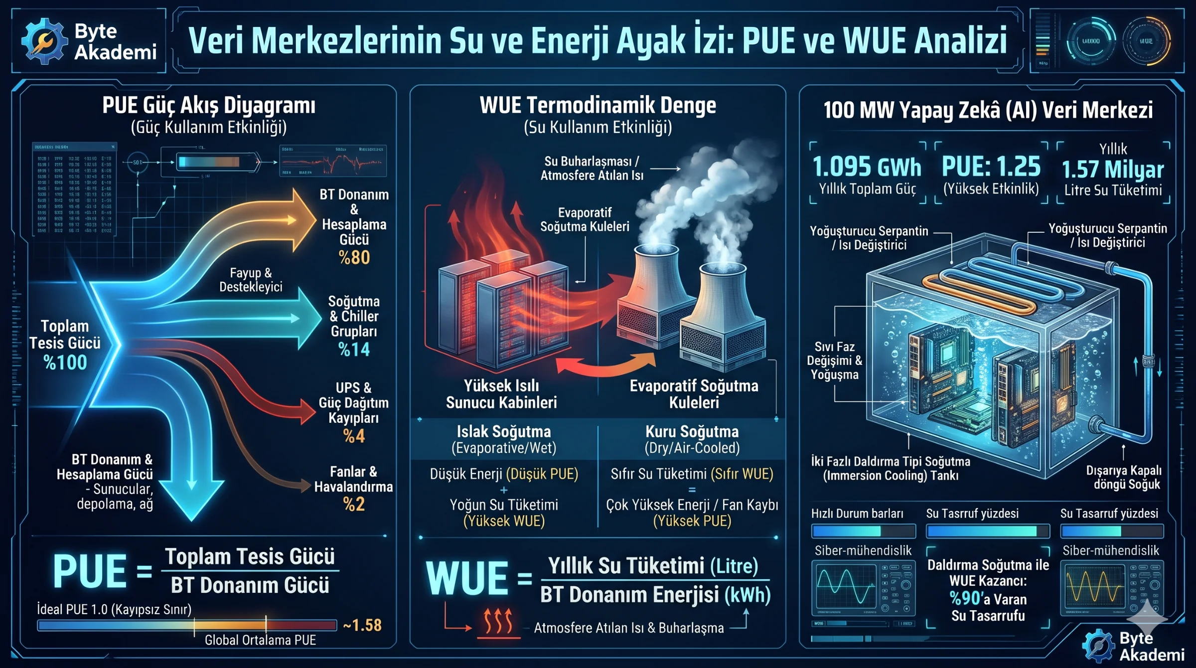
PUE = Total Facility Power / IT Equipment PowerWhere IT Equipment Power accounts strictly for computational workloads (CPUs, GPUs, storage arrays, switches), while Total Facility Power integrates transformer losses, uninterruptible power supply (UPS) conversions, facility lighting, and cooling infrastructure (chillers, pumps, fans).
- PUE = 1.0 (Theoretical Limit): Represents complete conversion where 100% of grid energy drives compute loads with zero cooling or power transformation losses.
- PUE = 1.1 - 1.2 (Hyperscale Tier): Advanced facilities utilizing free-air economizers and direct-to-chip liquid cooling loops in high-latitude environments.
- PUE = 1.5 - 1.8 (Enterprise Legacy Average): Typical configurations where up to 0.8 watts of auxiliary cooling and distribution energy support every single watt of compute work.
Compressing PUE metrics through evaporative cooling frequently conceals a severe thermodynamic trade-off: saving electrical kilowatt-hours by vaporizing millions of liters of potable water into the atmosphere.
2. Water Usage Effectiveness (WUE) & The Cooling Trade-Off
PUE optimization often introduces a severe hidden resource penalty: exchanging electrical grid power for freshwater consumption.
To reduce PUE from 1.5 toward 1.1 without consuming heavy compressor electricity, facilities deploy Evaporative Cooling Towers. Rather than running high-draw chillers, hot exhaust air passes across wet media, releasing heat via water evaporation:
WUE = Annual Facility Water Consumption (Liters) / IT Equipment Energy (kWh)Typical evaporative facilities maintain WUE figures between 1.5 and 2.5 L/kWh. Under this architecture, dissipating the thermal waste of a single kilowatt-hour of compute consumes up to two liters of potable water.
  [THERMODYNAMIC RESOURCE COUPLING]

  Dry Chiller Cooling      : [High Electrical Draw (PUE: 1.4 - 1.6)] <---> [Zero Water Evaporation (WUE: 0.0)]
  Evaporative Open Towers  : [Low Electrical Draw  (PUE: 1.1 - 1.2)] <---> [Heavy Water Loss (WUE: 2.0+ L/kWh)]
3. Metric Framework & 100 MW Facility Audit
Evaluating total physical resource consumption across an enterprise-scale 100 MW continuous IT compute deployment:
  [METRIC DEFINITIONS]

  PUE = Total Facility Energy / IT Energy
  WUE = Total Annual Water (Liters) / IT Energy (kWh)
  Annual IT Energy = 100,000 kW * 8,760 h = 876,000,000 kWh (876 GWh)

  ======================================================================
  [AUDIT: 100 MW HYPERSCALE FACILITY (PUE = 1.25, WUE = 1.8 L/kWh)]

  1. Total Grid Electrical Consumption:
     Total Energy = 876,000,000 kWh * 1.25 = 1,095,000,000 kWh (1,095 GWh/year)
     (Facility Overhead: 219 GWh/year auxiliary cooling dissipation)

  2. Annual Potable Water Evaporated:
     Water Footprint = 876,000,000 kWh * 1.8 L/kWh = 1,576,800,000 Liters/year
     (~630 Olympic-sized swimming pools of pure freshwater vaporized)
======================================================================Two-phase liquid immersion submerges server blades directly in non-conductive dielectric fluid with a low 50°C boiling threshold. Vaporized fluid condenses along closed internal heat exchangers and returns to liquid without external open evaporation, targeting PUEs below 1.05 while keeping WUE near absolute zero.