Marketing slogans boasting theoretical 46 Gbps wireless ceilings represent one of consumer networking's most prominent exaggerations. Upgrading to a premium Wi-Fi 7 (802.11be) router does not accelerate a standard 500 Mbps residential fiber pipeline, nor can it bypass legacy client radio bottlenecks.
Yet for applications requiring deterministic sub-millisecond latencies, un-congested spectral allocations, and massive intra-network throughput, Wi-Fi 7 introduces fundamental physical improvements over Wi-Fi 6. This analysis details the mechanics of Multi-Link Operation (MLO), 320 MHz channelization, 6 GHz electromagnetic attenuation through building materials, and a practical site survey test framework.
1. Under What Operating Conditions Is Wi-Fi 7 Warranted?
The justification for deploying Wi-Fi 7 relies entirely on local network density and deterministic latency parameters rather than peak ISP download rates:
- Intra-LAN High-Throughput Pipelines: Facilities running Network Attached Storage (NAS) fabrics, local high-bandwidth compute rendering, or wireless spatial computing headsets (e.g., Apple Vision Pro) demand wireless interfaces matching NVMe bus transfer speeds.
- Saturation of Legacy 2.4 GHz and 5 GHz Bands: In high-density multi-dwelling units (MDUs), 5 GHz spectrum channels suffer severe contention and Dynamic Frequency Selection (DFS) radar radar drops. The pristine 6 GHz band provides up to 1,200 MHz of clear, un-congested spectral space.
- Low-Jitter Real-Time Telemetry: Mission-critical workloads—competitive esports, high-frequency financial execution nodes, or industrial robotic automation—cannot tolerate bufferbloat or multi-packet drops.
Wi-Fi 7 does not merely amplify peak wireless throughput; through MLO and clean 6 GHz spectrum allocation, it brings deterministic Ethernet reliability to the airwaves.
2. Multi-Link Operation (MLO): Aggregated Radio Links
Prior generations bound client connections to a single discrete radio link. If interference saturated a 5 GHz channel, packets were stalled until back-off timers cleared.
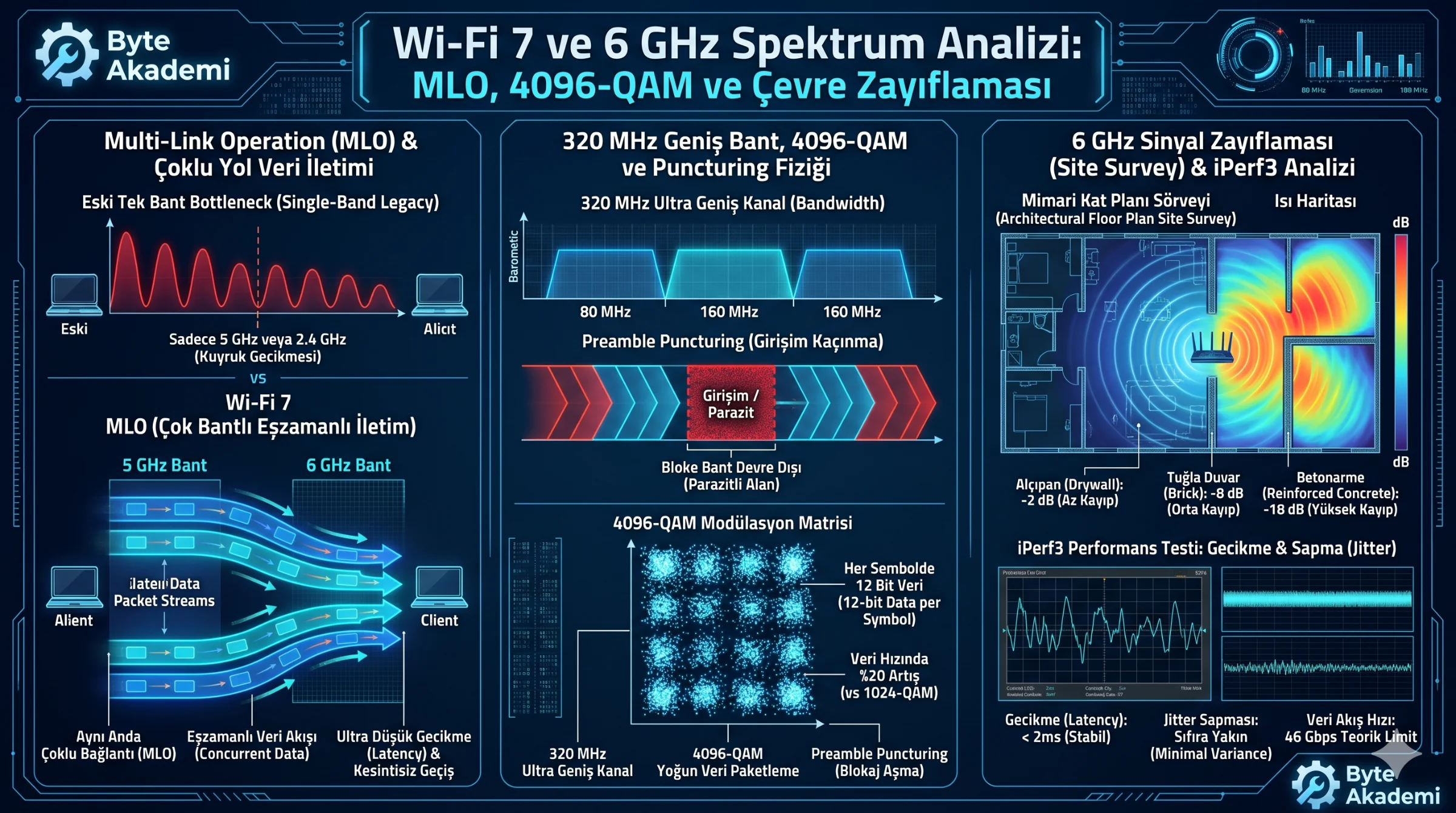
Wi-Fi 7 resolves this architectural bottleneck through Multi-Link Operation (MLO), enabling simultaneous multi-band transport across 5 GHz and 6 GHz spectrums:
- Simultaneous Transmit and Receive (STR): High-end client radios allocate dedicated front-end chains to transmit and receive across independent frequencies concurrently, approaching true full-duplex wireless transmission.
- Enhanced Multi-Link Single Radio (eMLSR): Cost-optimized clients monitor multiple links dynamically. As soon as a channel clears, packets route instantly across the vacant spectrum, suppressing jitter spikes.
3. 320 MHz Channelization & 4096-QAM Modulation
Spectral capacity is dictated by Shannon-Hartley channel capacity theorems. Wi-Fi 7 doubles maximum channel bandwidth to 320 MHz within the 6 GHz spectrum and elevates modulation to 4096-QAM:
- Bit Density Expansion: Moving from 1024-QAM to 4096-QAM raises constellation density from 10 bits/symbol to 12 bits/symbol, achieving an immediate 20% surge in raw physical PHY throughput.
- Preamble Puncturing: If narrowband interference encroaches on a 20 MHz segment of an active 320 MHz channel, Wi-Fi 7 slices out the congested sub-band while keeping the adjacent 300 MHz channel fully operational.
4. Electromagnetic Attenuation Across the 6 GHz Spectrum
Electromagnetic propagation dictates that attenuation scales with operating frequency. The tight wavelengths of 6 GHz radiation experience significant path loss through typical building materials:
| Barrier Material | 5 GHz Attenuation (dB) | 6 GHz Attenuation (dB) | Architectural Impact |
|---|---|---|---|
| Drywall / Wood Panel | 3 - 4 dB | 4 - 6 dB | Minimal throughput loss; 320 MHz sustained. |
| Solid Brick Wall | 6 - 8 dB | 9 - 13 dB | Modulation steps down; PHY rate halves. |
| Reinforced Concrete | 15 - 20 dB | 22 - 30 dB | 6 GHz link decouples; MLO reverts to 5 GHz. |
5. Site Survey Verification Plan
  [RF VALIDATION & BANDWIDTH AUDIT SCRIPT]

  Step 1: Local PHY Throughput (iPerf3)
  - Bind target endpoint to a 2.5 Gbps or 10 Gbps wired Ethernet port:
    Server command : iperf3 -s
    Client command : iperf3 -c [Server_IP] -P 8 -t 30

  Step 2: Jitter and Packet Drop Audit
  - Transmit continuous ICMP echo buffers directly to network gateway:
    Execution: ping [Gateway_IP] -c 1000
    Threshold: Median latency < 2 ms, Jitter < 1 ms, Zero drop.

  Step 3: 6 GHz RSSI Mapping
  - Conduct spatial survey across operating partitions:
    Line-of-Sight : -40 to -60 dBm (Sustains 4096-QAM / 320 MHz)
    Single Wall   : -65 to -72 dBm (Sustains 160 MHz fallback)
    Multi-Wall    : < -75 dBm (6 GHz drops out; fallback to 5 GHz legacy)