Throughout the journey from drawing an electrical installation design to the handover of a construction site, the most vital engineering step that directly determines the safety of life and property is the Foundation Earthing Calculation. Earthing does not merely carry fault current into the ground when an insulation failure occurs; thanks to the galvanised strip laid inside the building's foundation reinforcement, it creates a complete equipotential surface throughout the building and limits dangerous touch and step voltages (UL ≤ 50V).
In this article we examine how the foundation earthing calculation is carried out in a permit-stage design compliant with Türkiye's Elektrik Tesislerinde Topraklamalar Yönetmeliği (Regulation on Earthing in Electrical Installations): the logic behind the formulas, the mandatory vertical rod selection criteria based on floor area, and a step-by-step numerical example.
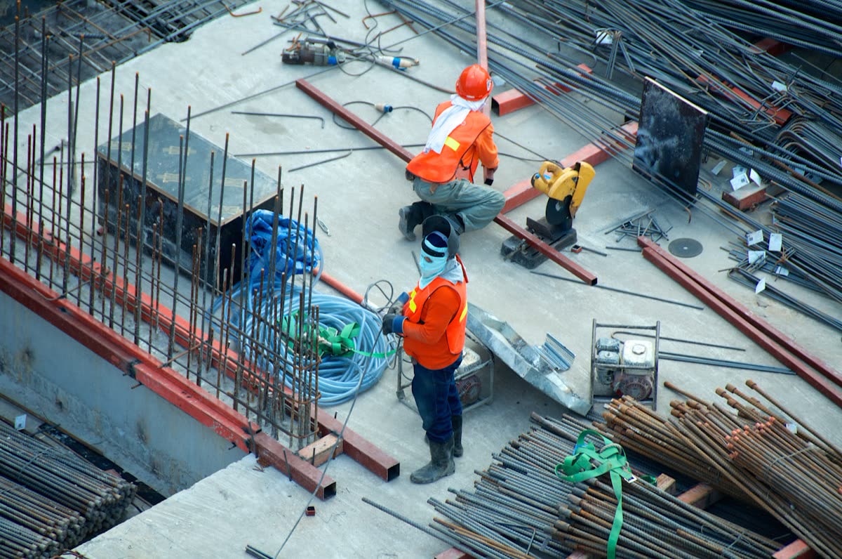
From the foundation to equipotential safety: galvanised strip and a vertical earth electrode installed on site.
Regulation on Earthing in Electrical Installations (Article 9): Foundation earthing is mandatory in all new buildings. The foundation earth electrode must be arranged as a closed ring and placed within the foundations of the building's external walls. If a strip conductor is used, it must be galvanised steel of at least 30x3.5 mm and mechanically clamped to the foundation reinforcement (mesh steel) at least every 2 metres.
1. Basic Quantities and the AutoCAD Drawing Rule
Before starting the calculation, the building's footprint geometry and soil parameters are determined:
- a, b [m]: Width and length of the building foundation (Building Footprint Area: A = a · b).
- ρe [Ω·m]: Soil resistivity (~100 Ω·m in moist clay, 500-1000 Ω·m in rocky ground).
- L [m]: Length of the earth electrode (perimeter length of the horizontal strip or length of the vertical rod).
- d [m]: Diameter of the buried conductor or electrode.
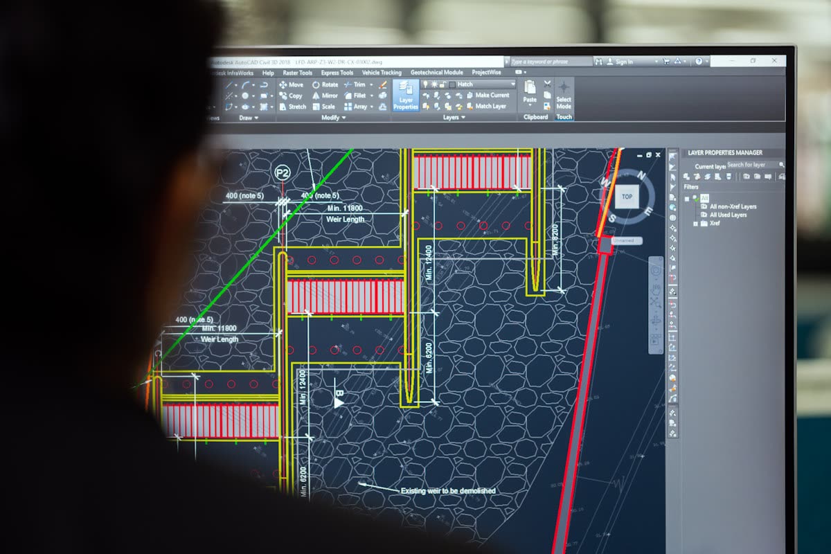
AutoCAD Design Tip: When drawing the foundation earthing plan, always create a dedicated "TOPRAKLAMA" (earthing) layer and draw the conductor as a closedPolyline (PL)loop. This lets you read the perimeter (L) and area (A) error-free with a single click from theProperties (PR / Ctrl+1)panel. To multiply your drawing and revision speed, don't forget to check out our guide AutoCAD Modify Menu: 21 Essential Editing Commands.
2. Calculation Steps and Mathematical Formulas
In a standard foundation earthing system, the horizontal galvanised strip and the vertical earth rods driven at the corners of the foundation work in parallel:
Achieving a low earth resistance alone does not guarantee safety! By regulation, the gas pipes, water services, heating/cooling lines and all metallic reinforcement entering the building must be connected to the Main Equipotential Busbar (Main Earthing Terminal). During a fault, this pulls the voltage at every point of the building to the same level (equipotential) and makes the build-up of a dangerous touch voltage physically impossible.
The formula that converts the building footprint into an equivalent circular area:
Dispersion resistance of earth electrodes driven vertically into the ground:
When several rods are connected in parallel, the total vertical resistance is divided by the number of rods (n): Total Rç = Rç / n.
Dispersion resistance of the galvanised strip laid as a ring inside the foundation concrete:
3. Number of Vertical Rods Based on Building Footprint
The table below gives the minimum number of vertical earth rods (n) to be driven at the building corners in order to support the horizontal strip ring and reach below the seasonal frost/drying layer:
| Building Footprint (A) | Minimum Number of Rods (n) | Standard Rod Length | Site Application |
|---|---|---|---|
| Up to 100 m² | At least 2 | 1.5 m - 2.0 m | At two opposite foundation corners |
| 100 - 1,000 m² | At least 4 | 2.0 m - 3.5 m | Symmetrically at the 4 outer foundation corners |
| 1,000 - 2,000 m² | At least 6 | 2.0 m - 3.5 m | Corners + expansion joints / middle axes |
| 2,000 - 5,000 m² | At least 8 | 3.5 m (or deep well) | Evenly spaced along the perimeter ring |
4. Total Equivalent Resistance (Re) and the Compliance Condition
The common rule that "earth resistance must always be below 2 Ohms" is outdated and incomplete. In modern regulations, the real requirement is that the earth resistance is coordinated with the protective device in use. In TT systems that use a residual current device (RCD) (30mA for life protection or 300mA for fire protection), the device trips at very small currents, so regulatory safety is theoretically achieved even at much higher resistance values. The real goal is to make sure the fault current can trip the protective device in the shortest possible time.
Since the horizontal ring earth and the parallel-connected vertical rods are in service at the same time, the total equivalent resistance of the system (Re) is calculated using the parallel equivalent relation:
For the calculated Re value to be verified against the regulation, it must satisfy the basic protection condition:
- UL: The permissible conventional touch voltage limit (taken as 50 Volts as standard in low-voltage installations).
- Ia: The operating current that makes the protective device disconnect the circuit within the specified time (e.g. 0.03 A for a 30 mA RCD).
5. Worked Numerical Example
Project Parameters:
- Building Dimensions: a = 20 m, b = 30 m (Area = 600 m², Strip Perimeter = 100 m)
- Soil: Moist Clay (ρe = 100 Ω·m)
- Vertical Rods: 4 pcs, Length = 2 m, Diameter = 20 mm (0.02 m)
1. Equivalent Diameter: D = √((4 · 600) / 3.14) ≈ 27.64 m
2. Horizontal Strip Resistance: Ry = (100 / (2 · 27.64)) + (100 / 100) = 1.81 + 1.00 = 2.81 Ω
3. Single Rod Resistance: Rç = (100 / (2 · 3.14 · 2)) · ln( (4 · 2) / 0.02 ) = 7.96 · 5.99 ≈ 47.68 Ω
4 Rods in Parallel: Total Rç = 47.68 / 4 = 11.92 Ω
4. Total Equivalent Resistance: Re = (11.92 · 2.81) / (11.92 + 2.81) = 33.50 / 14.73 ≈ 2.27 Ω
Result: 2.27 Ω fits comfortably within the < 2-5 Ω limits targeted in low-voltage distribution networks.
Conclusion: Engineering Discipline from the Drawing Board to the Site
The foundation earthing calculation is not a formality; it is the electrical ground reference of a building. When the perimeter measured with the correct layer and polyline in AutoCAD is combined with the right choice of soil resistivity, you avoid surprising measurement results on site.
Engineering means knowing what every line you draw becomes in the concrete poured on site, and tying safety to mathematics from the very first moment!
To lower the foundation earth resistance in your projects, do you prefer adding more vertical rods or using chemical ground enhancement materials (GEM / bentonite)? Share your experience in the comments!