As an electrical and electronics engineer inspecting the switchyards of industrial plants or residential distribution boards, one of the deadliest rules of thumb I come across most often is this: "We drove a copper rod into the ground, so the building's earthing is done." This approach is like taping a car's seat belt under the seat instead of anchoring it to the chassis and then saying "we've put the belt on." The mere physical presence of a green-yellow conductor in an installation does not mean that installation can protect human life.
Earthing is the art of keeping the touch voltage below the safe limit of 50 Volts by diverting static charges and phase-to-enclosure fault currents into a zero-impedance reference point (the earth) instead of through the parallel resistance of the human body. However, the only way to know whether this protection actually works is periodic Low Voltage (LV) Earthing Inspections carried out with instruments calibrated in line with the regulations. Let's dissect the anatomy of these inspections, from network types to loop impedance dynamics and from deadly measurement mistakes on site to legal standards, using a Source → Analysis → Conclusion discipline.
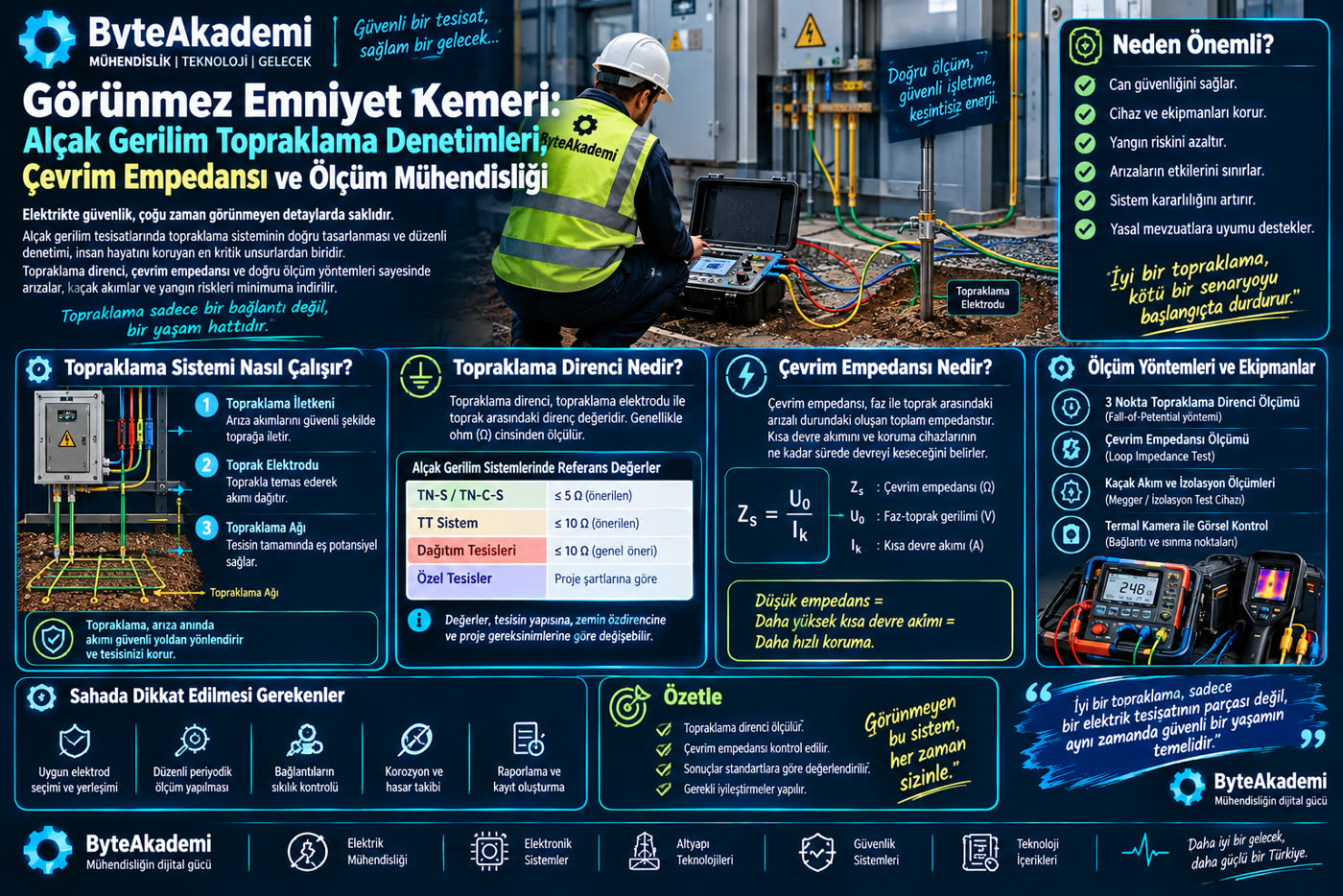
An earthing inspection is not just a single resistance reading; it is the verification of the entire loop impedance along the fault current's return path to the transformer star point.
1. Source and Core Criterion: The 50V Touch Voltage ($U_L$) Threshold
Under international standards (IEC 60364-4-41) and national regulations, the maximum touch voltage the human body can tolerate under dry conditions in alternating current is defined as $U_L = 50\text{ V}$ ($25\text{ V}$ in wet/damp locations).
When a phase conductor touches the frame of an electric motor, the job of the earthing system is to keep the voltage built up on the frame below these 50 Volts while carrying the fault current to earth, and to make the protective device in the circuit (fuse or residual current device) trip within the 0.2 to 0.4 seconds required by the standards. Depending on the system topology, this criterion splits mathematically into two:
Condition for TN Systems: Zs × Ia ≤ U0 &implies; t ≤ 0.4 s (Disconnection time verification)
Here $R_A$ is the dispersion resistance of the earth electrode, $I_{\Delta n}$ is the rated residual operating current of the RCD, $Z_s$ is the fault loop impedance, $I_a$ is the current that trips the protective device within the required time, and $U_0$ is the nominal phase-to-earth voltage (230V).
2. Technical Analysis: What Is Measured on Which Network?
The biggest engineering mistake in earthing inspections is applying the same measurement method to every building. The topology of the distribution network directly determines the measurement method:
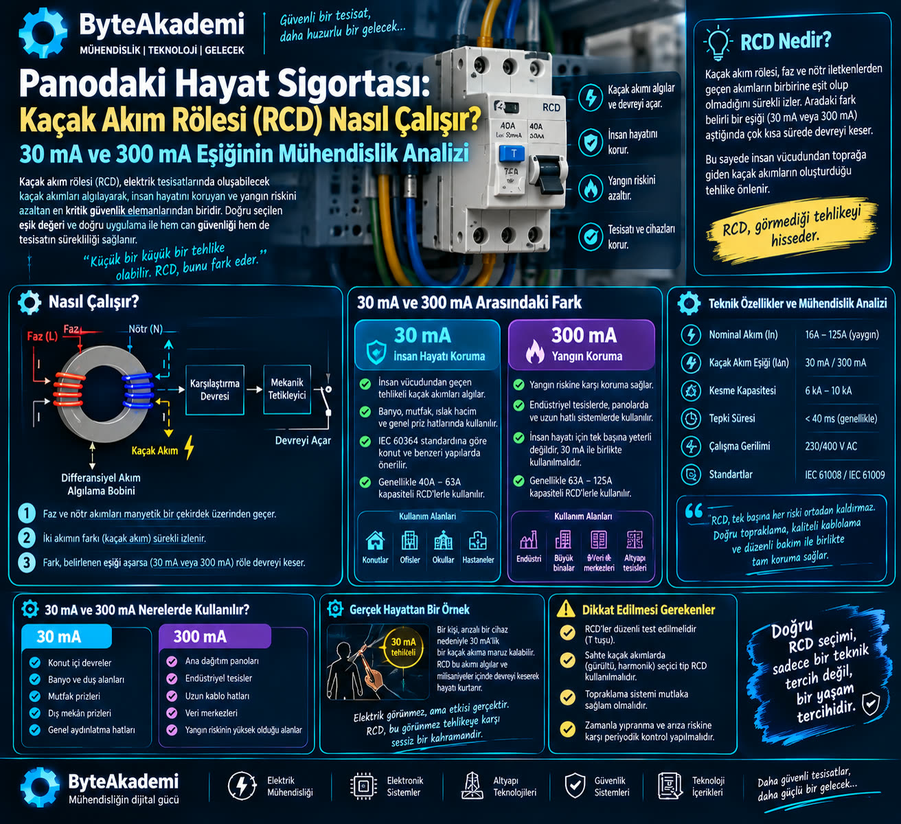
This is the system in which the transformer neutral is connected to the system earth, while the building is connected to a completely independent protective earth. Here the dispersion resistance of the ground itself is measured (Fall of Potential - the 62% rule). Current and potential probes are driven into the ground to determine the pure earth resistance of the electrode. As discussed in our earlier residual current device analysis, it is impossible to protect human life in a TT system without an RCD.
B. TN Networks (Neutral-Earthed / Utility Networks): The Loop Impedance TestIn industrial plants and urban networks, the protective conductor (PE) is connected directly to the transformer's neutral point. Here it is not the earth resistance but the Fault Loop Impedance that must be measured. The tester is plugged into the socket, and the milliohm-level resistance of the closed circuit running through the phase conductor, transformer winding, protective conductor and terminals is measured. It is then checked whether the calculated prospective short-circuit current ($I_k$) will magnetically trip the circuit breaker at the head of the line within 0.4 seconds.
Measurement Methods Used in Earthing Inspections
| Measurement Method | Target Parameter | Applicable Network | Critical Error Risk |
|---|---|---|---|
| Loop Impedance | Fault loop impedance ($Z_s$) and $I_k$ current | TN-S, TN-C-S Systems | False tripping during voltage fluctuations on the line |
| 3-Wire Fall of Potential | Dispersion resistance ($R_E$) | TT Systems / Lightning Protection | Overlapping zones of influence (spheres) of the probes |
| Continuity Test (200 mA) | Integrity of the PE protective conductor (≤ 0.2 Ω) | All Installations | Missing the contact resistance of oxidised terminals |
| Multimeter Voltage Test | Static neutral-to-earth voltage | INVALID METHOD | Guarantees nothing about resistance; it is misleading! |
3. Deadly Mistakes on Site and the Engineering Prescription
In our site inspections, there are two major misconceptions we encounter most often that directly threaten the safety of life:
- The "1 Volt Between Neutral and Earth, So the Earthing Is Great" Fallacy: Some electricians take an ordinary multimeter, measure between the neutral and earth of a socket, see 1-2 Volts and assume the earthing is sound. This value only shows the voltage drop on the neutral line; it gives zero information about the earth resistance of the line. Even if the earth conductor is left floating, you may statically see 0V there; but during a fault, 230V appears on that socket and electrocutes a person!
- Missing Equipotential Bonding: If the building's water pipes, natural gas pipes, lift rails and foundation reinforcement are not connected to the main earthing busbar (i.e. there is no equipotential busbar), then when an appliance develops a fault to its enclosure, a lethal potential difference arises between two different conductive surfaces.
- Corrosion and Galvanic Ageing: Galvanised strips or rods buried in the ground corrode within 5-10 years in acidic soils and lose their conductivity. That is why periodic inspection is not a formality but a physical necessity.
Conclusion: An Inspection Schedule That Saves Lives
Final Engineering Verdict: Under Türkiye's Elektrik Tesislerinde Topraklamalar Yönetmeliği (Regulation on Earthing in Electrical Installations), earthing inspections in industrial facilities and businesses must be carried out at least once a year, and for fixed operating equipment at least every 2-3 years, by authorised electrical engineers using calibrated test instruments with valid calibration certificates, and must be documented in a report.
Fake reports approved on paper don't save lives. Having the fault loop impedance of your installation actually measured, having the trip times of your residual current devices verified and ensuring equipotential balance are the greatest life insurance for your family, your employees and your facility.
- TS HD 60364-6 / IEC 60364-6: "Low-Voltage Electrical Installations - Part 6: Verification, Initial and Periodic Inspection Standards".
- TS HD 60364-4-41: "Safety in Electrical Installations - Protection Against Electric Shock and Touch Voltage Requirements".
- Official Gazette of the Republic of Türkiye (No. 24500): "Elektrik Tesislerinde Topraklamalar Yönetmeliği" (Regulation on Earthing in Electrical Installations) (21 August 2001).
- IEEE Std 81: "IEEE Guide for Measuring Earth Resistivity, Ground Impedance, and Earth Surface Potentials of a Grounding System".
What method was used for the last earthing measurement at your home or factory? Are you one of those who just measure voltage with a multimeter and move on, or do you rely on engineering reports made with a calibrated loop impedance tester? Share your experience in the comments!