When you push open the heavy steel door of a substation and step inside, you notice that faint smell of ozone hitting your face and the deep 50 Hz magnetic hum of the grid. If you work on the medium voltage (MV) side, there is one rule you must never forget: there is zero margin for error here; high voltage does not give second chances. A moment of distraction, a single skipped safety step or one handle turned in the wrong order can turn a switchgear panel worth hundreds of thousands of liras into the centre of a massive explosion within seconds.
What will save your life during operation or maintenance work in a substation is not luck; it is strict switching protocols, mechanical interlocks inside the panels and pre-checks carried out with iron discipline. In this guide we break down the sequence we must follow when de-energising and re-energising high-voltage switchgear, the fatal mistakes made in the field, and the functions of the 7 basic modular panel types that make up a substation. What's more, this article is the backbone of a much larger series: right after laying this foundation, we will examine each panel type in its own dedicated article, from circuit diagrams to secondary protection relays.
Switching in MV switchgear is an engineering discipline that requires mechanical interlocks and a strict switching sequence to be applied without exception.
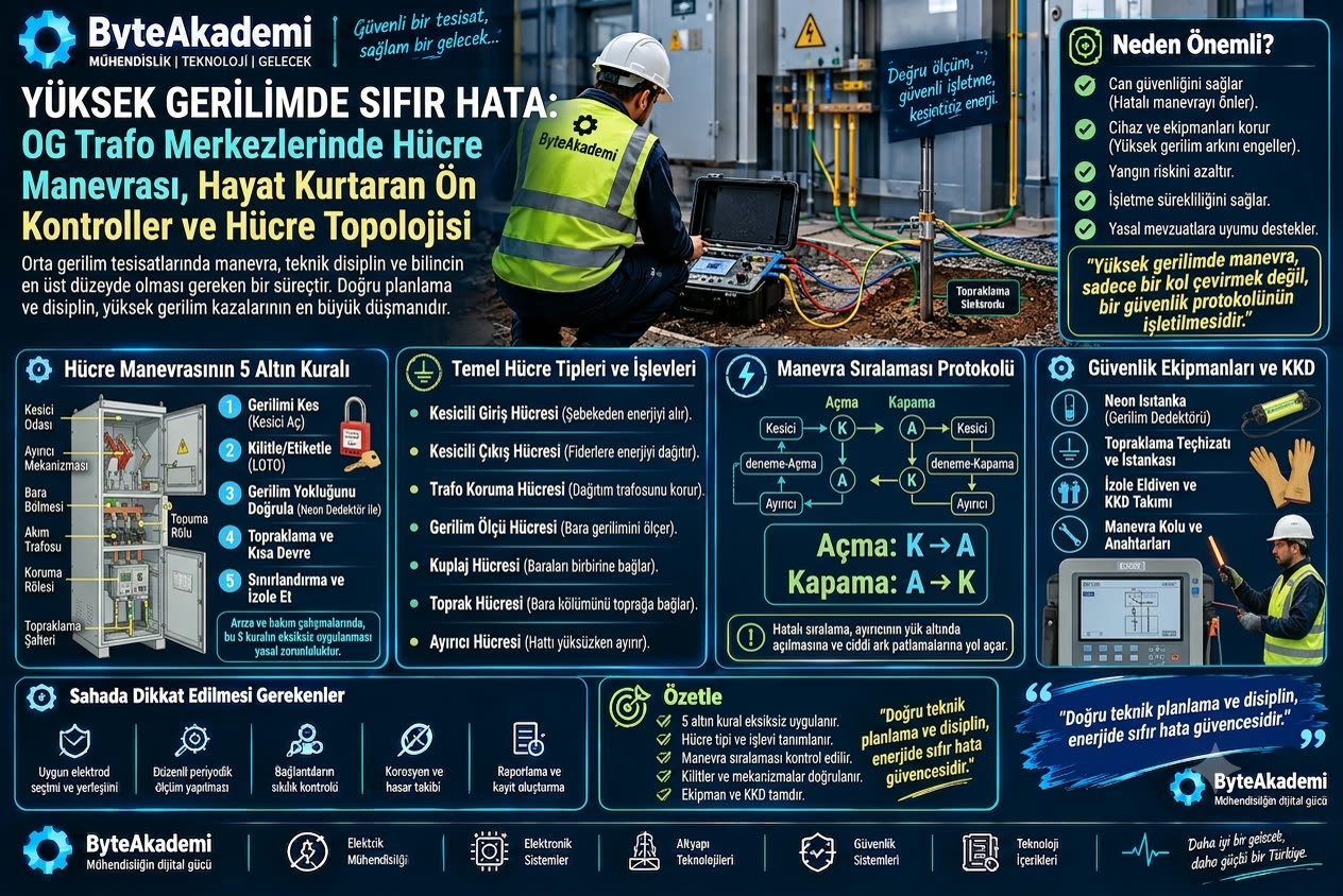
1. Before You Start Switching: The 5 Life-Saving Golden Rules
Before you lay a hand on a panel's operating handle, we must fully apply the "5 Golden Rules" set out both in national occupational safety legislation and in the European standard EN 50110-1:
- 1. Disconnect Completely: Open the circuit breaker of the relevant feeder to take the load off the circuit, then open the disconnector to create a physical, visible isolation gap.
- 2. Secure Against Re-energisation with Lockout/Tagout (LOTO): Fit a padlock to the disconnector and breaker mechanisms you have opened. Hang the warning sign "DANGER! WORK IN PROGRESS, DO NOT ENERGISE" on them. The key must stay with you.
- 3. Verify the Absence of Voltage Yourself: The capacitive voltage indicator lamps on the panel's front being off can never be accepted as sufficient on their own. Touch the busbar compartment or cable terminations with an MV Voltage Detector (neon hot stick) whose calibration is up to date, and confirm audibly and visually that the line is dead.
- 4. Earth and Short-Circuit: Once the absence of voltage is confirmed, close the panel's earthing switch, or short-circuit the line and connect it to earth with portable earthing sticks. This step eliminates any backfeed that might come from a remote point, as well as the residual capacitive static charge in the cable.
- 5. Barrier Off and Isolate the Work Area: Clearly separate areas with adjacent live panels or energised busbars using safety barriers, warning tape and insulating covers.
However many years of experience you have in substations, never carry out switching on your own. It is a vital rule to have a second qualified technician (an observer) with you who can open the main switch in an emergency, provide first aid and check each switching step against the written procedure.
2. The Unchanging Mathematics of Switching: The Sequence Protocol
There are two basic switching devices in medium voltage switchgear: the Circuit Breaker and the Disconnector. Because the circuit breaker has an arc-quenching chamber (vacuum or SF6), it can safely interrupt high load currents and short circuits. The disconnector, however, only provides visible physical separation of the circuit; it must never be opened under load! Otherwise, the massive arc that forms will blow the panel apart.
Step 1: OPEN the Circuit Breaker → Interrupt the load current and bring it to zero.
Step 2: OPEN the Line/Busbar Disconnector → Mechanically separate the now current-free circuit.
Step 3: Verify Absence of Voltage → Check each phase one by one with the neon detector/hot stick.
Step 4: CLOSE the Earthing Switch → Discharge the remaining capacitive static charge to earth and make it safe.
Step 1: OPEN the Earthing Switch → Remove the short-circuit bridge.
Step 2: CLOSE the Line/Busbar Disconnector → Prepare the physical path of the circuit.
Step 3: CLOSE the Circuit Breaker → Energise the load in the safe arc chamber.
3. The Modular Panel Family: The 7 Basic Building Blocks of a Substation
In a substation, each panel's role and equipment are completely different from the others. To switch correctly, you need to know by heart what each panel does:
MV Substation Modular Panel Topology
| Panel Type | Switching / Protection Devices | Main Role in the System |
|---|---|---|
| 1. Incoming Circuit Breaker Panel | Circuit Breaker + Disconnector + Current Transformer + Protection Relay | Safely receives the energy coming from the grid, energises the main busbar and protects the whole substation in a fault. |
| 2. Outgoing Circuit Breaker Panel | Circuit Breaker + Disconnector + Current Transformer + Toroidal (Earth Fault) Relay | Safely sends the energy on the busbar to another substation or to a large industrial feeder. |
| 3. Transformer Protection Circuit Breaker Panel | Circuit Breaker + Overcurrent / Short-Circuit & Buchholz Relay | Protects the distribution transformer against overload, winding short circuits and internal faults by tripping within milliseconds. |
| 4. Voltage Metering Panel | Voltage Transformers (VT) + MV Fuses | Steps the busbar voltage (34.5 kV) down to the 100V level that meters and relays can read; enables billing and frequency monitoring. |
| 5. Bus Coupler Panel | Bus Section Circuit Breaker + Disconnectors | Connects two separate, independent busbars; in ring networks it transfers the load to the other busbar when a feeder goes down. |
| 6. Earthing Panel | Earthing Switch + Busbar Connection | Fully earths the main busbar during maintenance of a busbar section, guaranteeing the safety of maintenance staff. |
| 7. Disconnector Panel | Load Break Switch / Rotary Disconnector | Used on branch lines that do not need a circuit breaker, to open and close the line when it is off-load or carrying small currents. |
Conclusion: The Roadmap for Our New Series
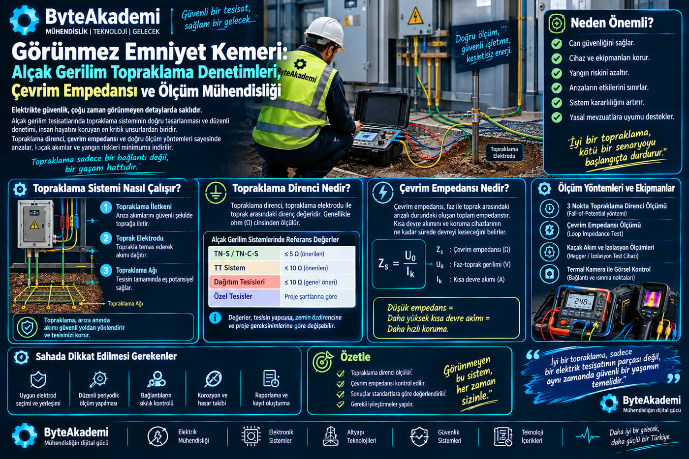
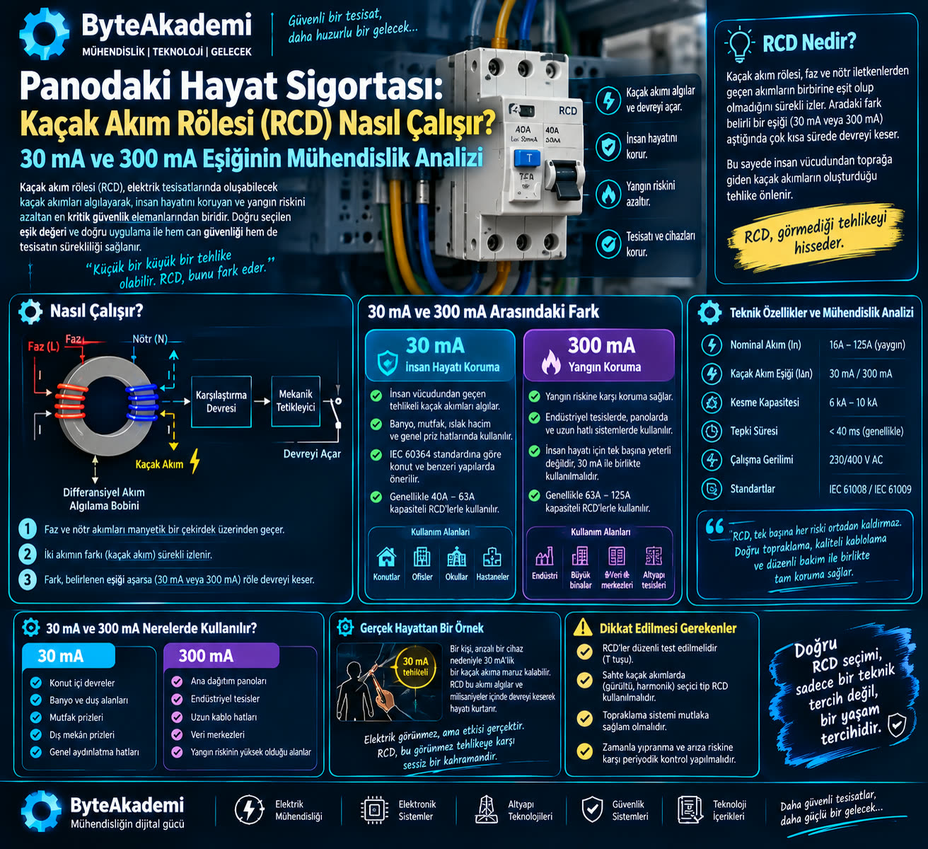
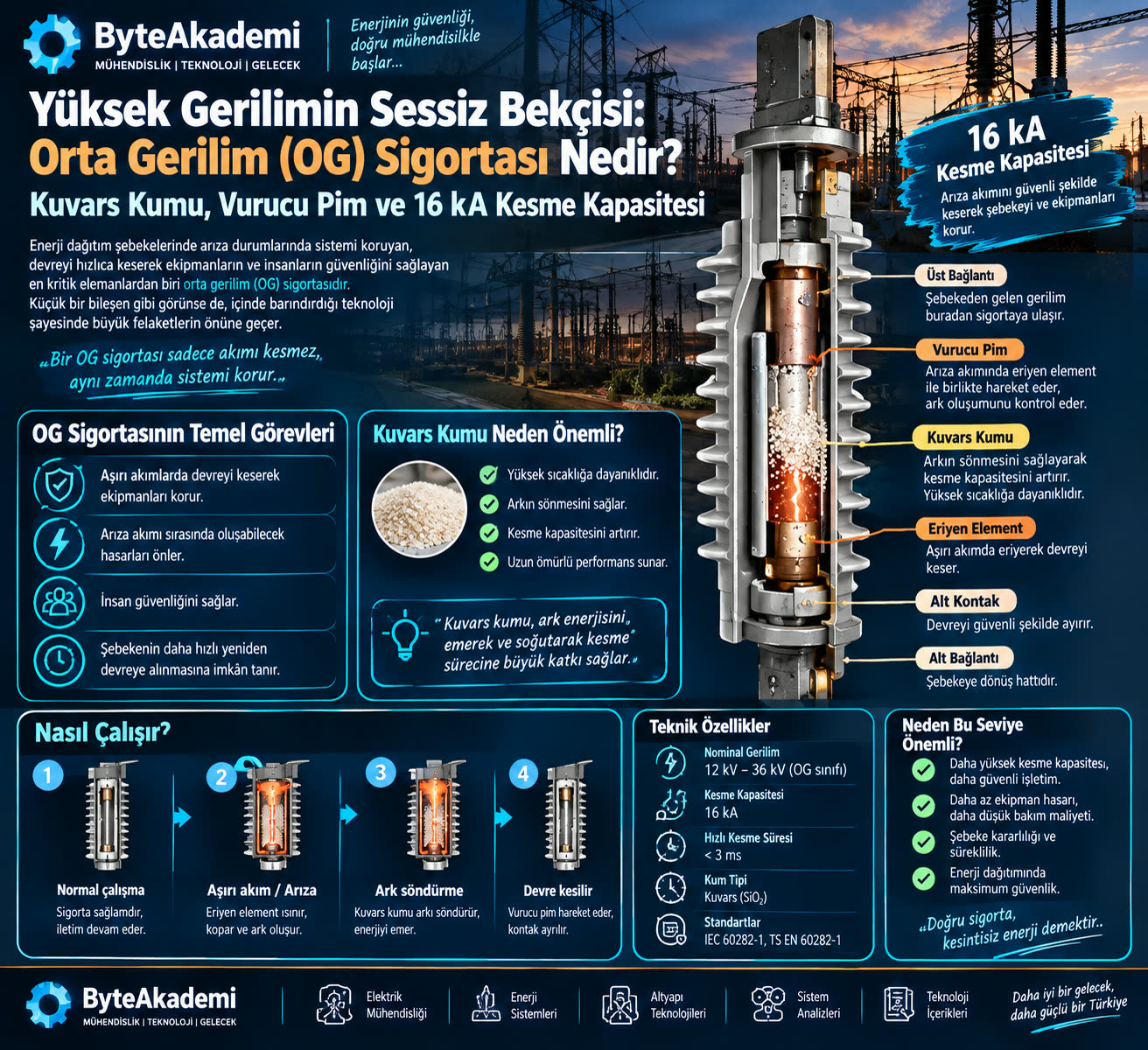
The medium voltage fuses and quartz sand physics and low voltage earthing inspections we covered in earlier articles were only specific protection nodes in this vast network.
With this article, we have written the constitution of the substation: we have set out the logic of switching, its sequence and the life-saving safety interlocks. In each of our upcoming articles, we will take the 7 panel types above one by one. Our first stop will be the heart of the network, the "Incoming Circuit Breaker Panel"; we will take apart every detail down to the last screw, from the arc chamber of its vacuum circuit breaker to the current transformer secondary connections and overcurrent relay setting calculations.
- IEC 62271-200: "High-voltage switchgear and controlgear - Part 200: AC metal-enclosed switchgear and controlgear for rated voltages above 1 kV and up to and including 52 kV".
- EN 50110-1: "Operation of electrical installations - General safety requirements & Five Safety Rules".
- TEİAŞ / TEDAŞ (Turkish transmission and distribution utilities): "İş Sağlığı ve Güvenliği Yönetmeliği - Yüksek Gerilim Tesislerinde Manevra Yönergesi" (Occupational Health and Safety Regulation - Switching Directive for High Voltage Installations).
- IEEE Std C37.20.2: "IEEE Standard for Metal-Clad Switchgear".
Which indicator on the panel do you check first before you start switching? Do you have an interesting switching experience, or a near miss, from the field? We look forward to your comments on the first step of our series!