At the heart of the vast grid that carries electrical energy from power plants all the way to our sockets sits a single family of machines: Transformers. Without these static electrical machines, which have no moving mechanical parts and work purely on Faraday's principle of electromagnetic induction, carrying energy hundreds of kilometres would be physically impossible.
When you go out into the field with the eyes of an electrical and electronics engineer, you see that transformers are not just ordinary units that step voltage up or down. According to where they sit in the grid, how they are loaded and what electrical function they serve, transformers fall into three main engineering disciplines.
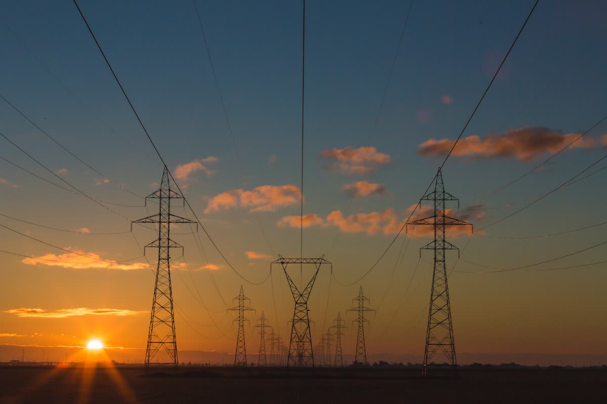
The energy backbone from power plant to socket: high-voltage transmission lines and transformer substations.
1. Power Transformers
Power transformers are the main arteries of the grid. Their job is to manage the transfer of energy between generating plants and the main transmission network (switchyards) with minimal losses. They typically operate at very high voltage levels such as 154 kV or 380 kV, with ratings between 50 MVA and 1000 MVA.
Because these transformers carry the main load of the grid directly, they mostly run close to full capacity (100% base load). As we covered in our earlier analysis, Engineering Features of Generator Step-Up Transformers (GSU), their winding mechanical strength, dynamic short-circuit forces and forced-oil-circulation (OFAF/ODAF) cooling architectures are completely different from those of standard transformers.
2. Distribution Transformers
These are the end devices in the field that step the medium voltage coming from the main substations at city entrances (34.5 kV under the Turkish standard) down to the low voltage usable in homes and industrial facilities (400 V phase-to-phase / 230 V phase-to-neutral). They are the final bridge between the distribution company and the end user.
- Load Variation and Core Losses: Unlike power transformers, distribution transformers do not run at a constant load 24 hours a day. Load falls to a minimum at night and peaks in the evening. That is why keeping "no-load losses (iron losses)" to a minimum is fundamental in their engineering design.
- Dyn11 Connection and Neutral Safety: They are usually connected delta on the primary and star on the secondary (Dyn11). The system neutral taken from the star point is the foundation of a safe electrical infrastructure. The quality of this point's earth connection works in direct sync with the equipotential safety network we detail in our Guide to Foundation Earthing Calculations in Electrical Projects.
3. Special Transformers: Metering, Protection and Regulation
In power transmission, converting voltage is not enough; you also need to read the electrical parameters on the line, bill for them, and trip the circuit breakers when the system develops a fault. Since you cannot connect 34,500 volts or 2,000 amperes directly to standard measuring instruments, special transformers come into play:
They step high or medium voltage down to the standard 100 V or 110 V level that protection relays and meters can read safely. They are connected in parallel with the network. Their ratings are very small (typically 15-100 VA). Their secondary circuits must never be short-circuited; otherwise the overcurrent will burn out the transformer windings.
3.2. Current Transformers (CT)They proportionally reduce currents of hundreds or thousands of amperes flowing through the main conductor to the standard 5 A or 1 A level that measuring devices can handle (e.g. 600/5 A). They are connected in series with the main line and act as the sensors of the protection system.
3.3. AutotransformersThey do not have two separate windings for primary and secondary; the voltage is stepped through a single shared magnetic winding. Compared with classic two-winding transformers, they are smaller, lighter and extremely efficient. But their most critical drawback is this: there is no galvanic isolation between primary and secondary. That is why they are only used at controlled intermediate stages where voltage matching is all that is needed.
While short-circuiting a voltage transformer leads to disaster, with current transformers (CTs) it is exactly the opposite: while primary current is flowing, the secondary circuit of a current transformer must never be left open. If the secondary is left open, the entire primary current becomes magnetising current that drives the magnetic core into saturation. The excessive magnetic flux in the core induces a lethal voltage in the kilovolt (kV) range across the open secondary terminals. This punctures the insulation, can make the transformer explode and puts personnel's lives at risk. If a device connected to a current transformer is to be removed, the secondary terminals must always be short-circuited first with a dedicated shorting link.
Conclusion
Transformers are not merely equipment that raises and lowers voltage; they are the engineering building blocks that ensure grid balance, measurement accuracy and personnel safety. Power transformers provide robustness, distribution transformers provide dynamic load flexibility, and special instrument transformers form the grid's nervous system.
In your projects or site tests, have you ever run into reversed CT polarity (P1-P2, S1-S2) or an open secondary? Share your field experiences in the comments!