As an electrical and electronics engineer, whenever I walk into a medium voltage (MV) distribution centre or a transformer kiosk, my eye goes first to the protection devices inside the switchgear panels. Most people think safety in the power grid comes down to huge SF6 gas or vacuum circuit breakers alone. Yet the cheapest but most critical passive safety shield in the system, which can open the circuit during overcurrent and short circuits even faster than mechanical breakers, is the Current-Limiting Medium Voltage (MV) Fuse.
When you hold one in the field, with its porcelain or resin body it looks like a large tube; these devices protect transformers, cable lines and sensitive metering panels from short-circuit blasts of thousands of amperes. So how can a tube with a tiny rated current like "36 kV / 2A" printed on its body swallow a massive 16,000-ampere (1000 MVA) short-circuit explosion within milliseconds, without letting a single spark escape? Let's examine this marvel of high-voltage protection in full engineering detail, following the Source → Analysis → Conclusion principle.
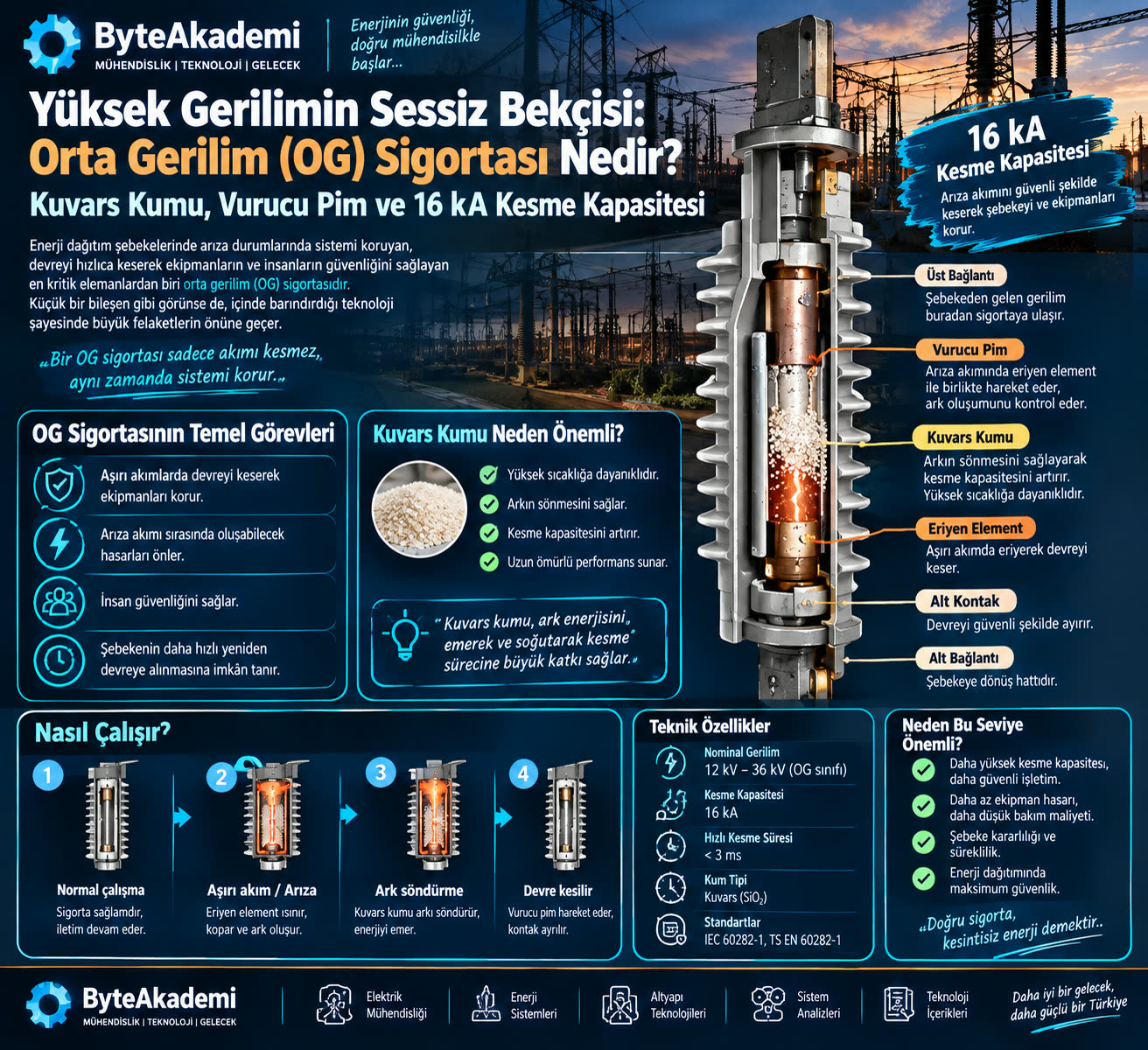
An MV fuse with a high rated breaking capacity: with its pure quartz sand filling and silver wire winding, it limits the fault current without going into thermal shock.
1. Source and Arc-Quenching Physics: The Secret of Quartz Sand
When a short circuit occurs at medium voltage level (1 kV – 36 kV), the current through the circuit tears through the dielectric strength of the air and forms a plasma arc at thousands of degrees. If that arc forms in open air, it blows the panel apart and can destroy the whole switchgear room. The real engineering intelligence inside an MV fuse lies in its high-purity chemical quartz sand (SiO2):
- The Melting Silver Element: Inside the fuse body there are pure silver (Ag) strips wound on a ceramic former with a special star-shaped profile. When short-circuit current flows, the silver melts and vaporises within milliseconds.
- Fulgurite (Vitrification): The vaporised metal plasma comes into contact with the granular quartz sand surrounding it. The quartz sand absorbs the energy and heat of the arc, instantly melting and turning to glass (forming a fulgurite tube).
- Resistance Surge: The molten glass mass becomes an excellent insulator; it artificially drives the arc resistance sky-high and extinguishes the current within the first quarter cycle, without waiting for the natural current zero (the current-limiting effect). Not a single flicker of flame escapes the body.
2. Technical Parameter Analysis: Why 36 kV / 2A Is Not for a Power Transformer
The "36 kV / 2A" marking we often see on labels in the field can confuse young engineers and technicians who are new to the profession: "Can a huge 1000 kVA transformer really be protected with 2 amps?"
The answer: absolutely not! The primary rated current of a standard power transformer operating at 36 kV is tens of amperes, and its protection fuses are chosen as 10A, 16A, 25A or 40A depending on the transformer rating. The special 2-ampere cartridge we examine in the image is made not for power transformers but for the primary winding protection of the Voltage Transformers (VTs) inside the panel.
The 1000 MVA rated breaking capacity on the label certifies that, even though the fuse's rated operating current is only 2A, it can safely interrupt a terrifying short-circuit current of about 16,000 amperes (16 kA) that could come from the interconnected transmission grid behind it, without shattering the tube. This margin is where the real power of high-voltage engineering lies.
MV Protection Devices Comparison Matrix
| Technical Parameter | MV Current-Limiting Fuse | MV Circuit Breaker (Vacuum / SF6) |
|---|---|---|
| Opening / Interrupting Time | < 5 - 10 ms (Before the first current peak) | 40 - 80 ms (Relay + Mechanical opening) |
| Current Limiting (I²t Reduction) | Very High (Eliminates thermal stress) | None (Full fault current flows) |
| Cost & Maintenance | Low cost, zero maintenance (Single use) | High CapEx + Periodic mechanical maintenance |
| Purpose | Primary short-circuit protection for transformers, cables and VTs | Main incoming/outgoing, line switching and selectivity |
3. The Striker Pin Trap and Field Experience
At the top of an MV fuse, inside a metal cap, sits the Striker Pin, held by a spring mechanism. When the high-resistance auxiliary wire inside melts, the mechanical spring is released and the pin shoots out with considerable force (typically 50 N to 120 N).
This pin has two vital jobs:
- Mechanical Visual Indicator: It shows through the inspection window whether the fuse has blown, without opening the panel door.
- Tripping the Load Break Switch: In three-phase systems, to stop motors or the transformer from burning out on two phases when only one phase's fuse blows, the ejected pin strikes a mechanical latch in the panel and instantly opens all 3 phases of the load break switch at once.
The Field Engineer's Golden Rule: After a fault, many operators look at the panel, say "The pin hasn't popped out, so the fuse must be fine," and try to re-energise the system. This is a fatal mistake! In low-current faults caused by overload or ageing, the mechanical pin can sometimes stay stuck, or its spring may not push it all the way out, even though the silver has melted. In the field, the condition of an MV fuse is never judged by looking at the pin alone. Once the panel has been de-energised and earthed, the fuse should be removed from its holder and its continuity confirmed beyond doubt with an ohmic resistance test using a multimeter or micro-ohmmeter.
- IEC 60282-1: "High-voltage fuses - Part 1: Current-limiting fuses" (International Standard for Current-Limiting MV Fuses).
- DIN 43625: "High-voltage fuses; rated voltages 3.6 to 36 kV; dimensions for fuse-links" (Dimensional and Mechanical Standards).
- TEDAŞ / TEİAŞ (Turkish distribution and transmission utilities): "Orta Gerilim Dağıtım Şebekeleri Koruma Elemanları ve Sigorta Seçim Şartnamesi" (Specification for Protection Devices and Fuse Selection in MV Distribution Networks).
- IEEE Std C37.47: "Specifications for High-Voltage Current-Limiting Type Distribution Class Fuses".
At your facility, do you replace a blown MV fuse just by looking at the ejected pin, or do you make it mandatory to earth the panel and run a resistance test with a multimeter? Share your field experiences in the comments!